A bias current programmable circuit

A bias current and current programming technology, applied in the direction of adjusting electrical variables, instruments, control/regulation systems, etc., can solve the problems of limited circuit minimum supply voltage, increase circuit complexity, influence, etc., and achieve stable and reliable bias current , small cost, and small bias current deviation range

Active Publication Date: 2022-07-12
CHENGDU AMBIT TECH CO LTD
View PDF2 Cites 0 Cited by
  • Summary
  • Abstract
  • Description
  • Claims
  • Application Information

AI Technical Summary

Problems solved by technology

However, in the traditional practice, the PTAT bias current generated by the reference module varies greatly under the corner of the chip process, and is limited by the minimum supply voltage of the reference module, and the minimum supply voltage of the PTAT bias current will also Limited; while the generation of CTAT current will increase the complexity of the circuit, its current deviation mainly comes from the deviation of the internal resistance of the chip, the resistance value will be affected by temperature and process angle, and will also be limited by the minimum supply voltage of the circuit

Method used


Image

  • A bias current programmable circuit
  • A bias current programmable circuit
  • A bias current programmable circuit

Examples


Embodiment

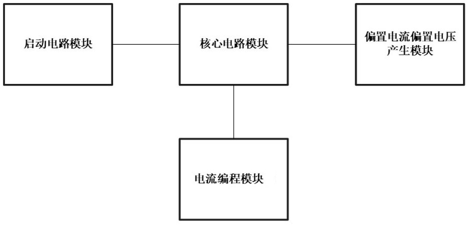
[0027] combine figure 1 As shown, a bias current programmable circuit includes a startup circuit module connected to a supply voltage, a core circuit module and a bias current bias voltage generation module, and a current programming module, wherein:

[0028] a startup circuit module, connected to the core circuit module, for generating a pulse signal and inputting it to the core circuit module when powered on;

[0029] a core circuit module, connected to the current programming module, for triggering normal operation by the pulse signal, and outputting a bias current to the current programming module;

[0030] A bias current bias voltage generating module, connected to the core circuit module, used for sampling the bias current generated by the core circuit module, using the bias current to generate the bias voltage, and combining the obtained bias current and bias external voltage output;

[0031]The current programming module is used to change the equivalent resistance of...

Embodiment 2

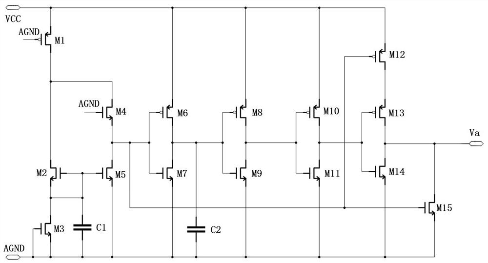
[0034] On the basis of Example 1, combined with figure 2 As shown, the startup circuit module includes a MOS transistor M1, the source of the MOS transistor M1 is connected to the supply voltage, the drain of the MOS transistor M1 is connected to the drains of the MOS transistor M2 and the MOS transistor M4, and the source of the MOS transistor M4 is connected to The drain of the MOS transistor M5, the gate of the MOS transistor M5 is connected to the gate and source of the MOS transistor M2 and the first end of the capacitor C1, the source of the MOS transistor M2 is connected to the drain of the MOS transistor M3, and the second of the capacitor C1 is connected to the drain of the MOS transistor M3. The terminal, the source and gate of the MOS tube M3, the source of the MOS tube M5, the gate of the MOS tube M1 and the gate of the MOS tube M4 are all grounded; the source of the MOS tube M4 is also connected to the gate of the MOS tube M6, The gate of the MOS tube M7, the gat...

Embodiment 3

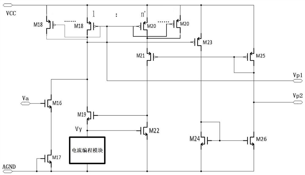
[0037] On the basis of embodiment 1 or 2, combined with image 3 As shown, the core circuit module includes MOS transistors M16, m parallel MOS transistors M18 and p parallel MOS transistors M20, where m and p are both positive integers and p is an integer multiple of m (eg m:p=1 : n'), the gate of the MOS tube M16 is connected to the output end of the startup circuit module (ie, connected to the pulse signal Va), and the drain of the MOS tube M16 is connected to the drain and gate of each MOS tube M18, each The gate of the MOS transistor M20, the gate of the MOS transistor M23 and the drain of the MOS transistor M19 are connected to the bias current bias voltage generating module as the first voltage output terminal, and the drain of each MOS transistor M20 is connected to the MOS transistor The source of M21, the drain of MOS transistor M21 are connected to the gate of MOS transistor M19 and the drain of MOS transistor M22, the gate of MOS transistor M22 is connected to the ...


PUM


Abstract

The invention discloses a bias current programmable circuit, which relates to the field of chip technology, comprising a startup circuit module connected with a power supply voltage, a core circuit module and a bias current bias voltage generating module, wherein the core circuit module is connected with a current programming module, wherein The startup circuit module is used to generate a pulse signal and input it to the core circuit when it is powered on; the core circuit module is triggered by the pulse signal to work normally and output the bias current to the current programming module; the bias current bias voltage generation module generates the core circuit module The bias current is sampled, and the bias current is used to generate the bias voltage and output the obtained bias voltage and bias current to the outside; the current programming module is used to change the magnitude of the bias current generated by the core circuit module. The invention can work under a lower power supply voltage, has stable and reliable structure, can be used as the bias current of the reference module in the reference circuit, and has a power-on start-up function, and the bias current error is small.

Description

technical field [0001] The invention relates to the field of chip technology, in particular, to a bias current programmable circuit. Background technique [0002] There are bias voltage and bias current in the chip containing power module. The bias current generally uses the current proportional to the absolute temperature (PTAT current) in the reference module, and some circuits with higher requirements will use the reference module to generate The reference voltage is divided by a resistor to obtain the constant current current (CTAT current). However, in the traditional practice, the PTAT bias current generated by the reference module has a large variation range under the process corner of the chip process, and is limited by the minimum supply voltage of the reference module, the minimum supply voltage of the PTAT bias current will also However, the generation of CTAT current will increase the circuit complexity. The current deviation mainly comes from the deviation of t...

Claims


Application Information

Patent Timeline
Patent Type & Authority Patents(China)
IPC IPC(8): G05F1/56
CPCG05F1/56
Inventor 龚加伟张军
Owner CHENGDU AMBIT TECH CO LTD
Why Eureka
Try Eureka