Slide rail tool free mounting frame for server

A mounting bracket, tool-free technology, applied in the direction of support structure installation, rack/frame structure, etc., can solve the problems of low work efficiency, inconvenient installation work, etc., and achieve the effect of convenient operation, simple structure, and tool-free installation.

Active Publication Date: 2012-09-26
雅固拉国际精密工业(苏州)有限公司
View PDF5 Cites 31 Cited by
  • Summary
  • Abstract
  • Description
  • Claims
  • Application Information

AI Technical Summary

Problems solved by technology

In this way, the use of tools will bring inconvenience to the installation wor

Method used


Image

  • Slide rail tool free mounting frame for server
  • Slide rail tool free mounting frame for server
  • Slide rail tool free mounting frame for server

Examples


Embodiment 1

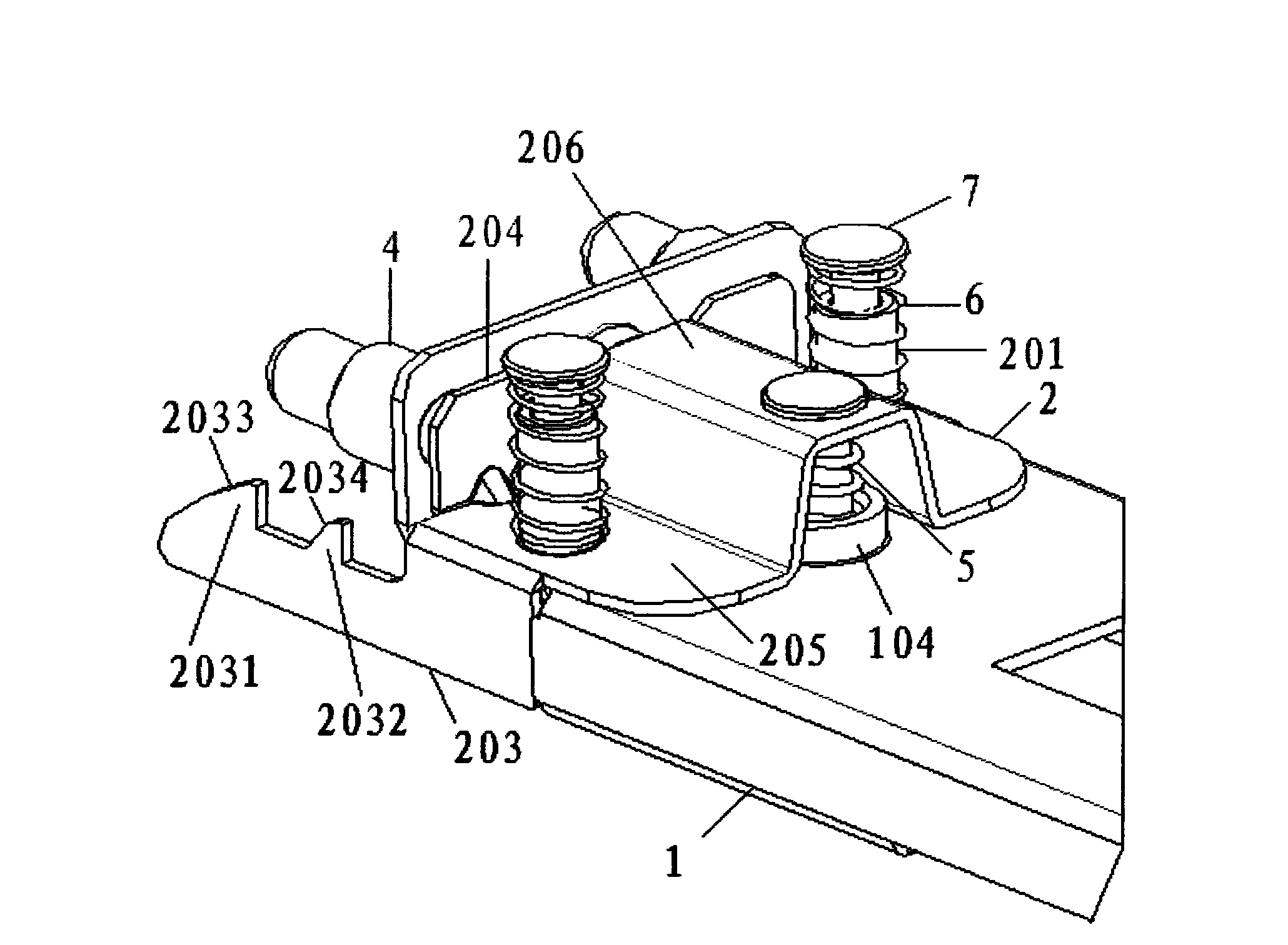
[0042] The following is attached image 3 , 4 , 5 and 6 are described in detail to the present embodiment:

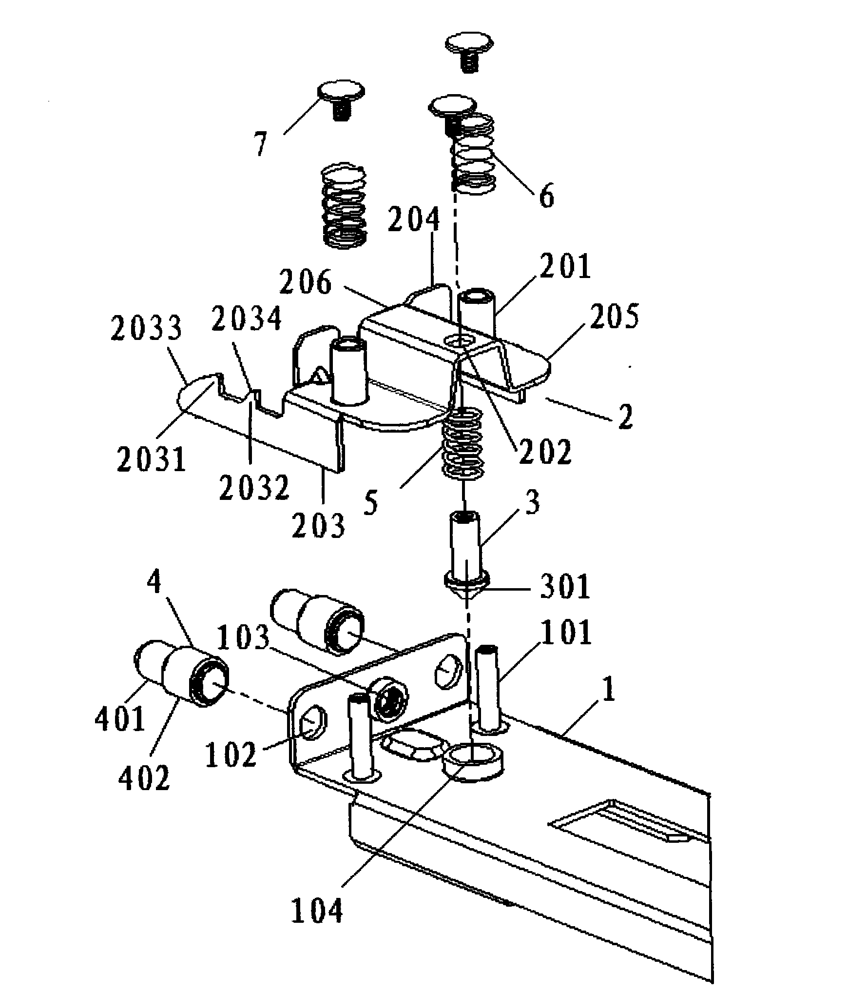
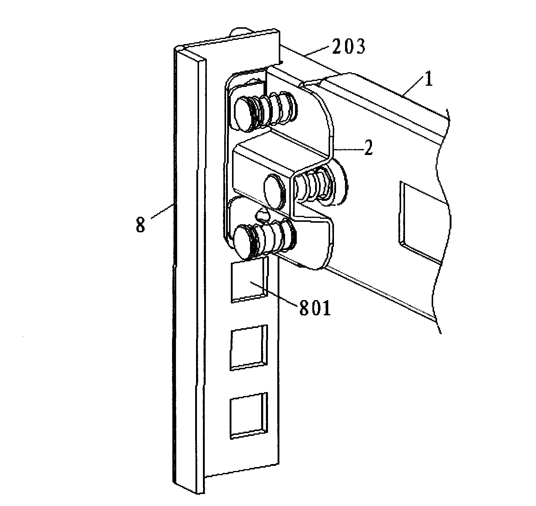
[0043] see image 3 with Figure 4 As shown, the rack installation hole 801 on the rack 8 is a square hole of 9.5mm*9.5mm, and the diameter of the square hole can accommodate the second positioning cylinder 402 .

[0044] The distance between the two rack positioning columns 4 of the tool-free mounting bracket for server slide rails in this embodiment can ensure that the two rack positioning columns 4 fall into different positions on the rack 8 for rack installation. In the hole 801, when installing, align the frame positioning column 4 with the frame mounting hole 801, and then push it forward. During the process of pushing, the vertical plate of the frame 8 will first touch the The first hook tooth 2031, due to the setting of the slope 2033, the frame lifting hook 2 will be pushed up, when the vertical plate of the frame 8 passes over the first hook tooth 2031, du...

Embodiment 2

[0049] The following is attached Figure 7 with Figure 8 The present embodiment is described in detail:

[0050] see Figure 7 with Figure 8 As shown, the rack mounting hole 801 on the rack 8 is a round hole with a diameter of 7.2 mm, and the size of the round hole can accommodate the first positioning cylinder 401 .

[0051] The distance between the two rack positioning columns 4 of the tool-free mounting bracket for server slide rails in this embodiment can ensure that the two rack positioning columns 4 fall into different positions on the rack 8 for rack installation. In the hole 801, the installation process is the same as the installation process in Embodiment 1. Since the rack installation hole 801 can only accommodate the first positioning column 401, the vertical plate of the rack 8 will be formed by the first positioning column 401. A hook tooth 2031 bites.

[0052] When the server slide rail tool-free installation bracket of this embodiment needs to be disasse...

Embodiment 3

[0054] The following is attached Figure 9 with Figure 10 The present embodiment is described in detail:

[0055] see Figure 9 with Figure 10 As shown, the rack installation hole 801 on the rack 8 is a threaded hole of M5-M6, and the diameter of the threaded hole is smaller than the diameter of the first positioning cylinder 401 .

[0056] The distance between the two rack positioning posts 4 of the tool-free mounting bracket for the server slide rail in this embodiment can ensure that the two rack positioning posts 4 are in the rack mounting holes at different positions on the rack 8 801.

[0057] When installing the server slide rail tool-free mounting bracket of this embodiment on the rack 8, it is necessary to use fixing screws 9. During operation, align the rack positioning posts 4 with the rack mounting holes 801 , since the end face of the first positioning cylinder 401 is provided with a screw hole, the fixing screw 9 can be screwed into the frame mounting hole...


PUM


Abstract

The invention provides a slide rail tool free mounting frame for a server. The slide rail tool free mounting frame comprises a pair of frame positioning columns arranged on a slide rail back mounting frame and a frame floating hook. The frame floating hook includes a pair of hooks respectively arranged on a pair of wings which are respectively provided with slide guide sleeves and are in fixed connection through an 'arch door' shaped bending piece. The slide rail back mounting frame is fixed with two slide guide columns which are sleeved in the slide guide sleeves and are in fixed connection through limit screws. First return springs are arranged on the slide guide sleeves and between the wings and the limit screws. The slide rail back mounting frame also is provided with a floating pin hole used for placing a floating pin. One end of the floating pin is connected to the 'arch door' shaped bending piece through the limit screws, and the other end of the floating pin is a conical head arranged in the floating pin hole. Second return springs are arranged on the floating pin and between an end face of the conical head and the limit screws. According to the slide rail tool free mounting frame, the tool free installation of a slide rail for the server is realized, that an operator completes disassembly in front of a server frame is realized, a structure is simple, and operation is convenient.

Description

technical field [0001] The invention relates to a mounting bracket for a slide rail for a server, in particular to a tool-free mounting bracket for a slide rail for a server. Background technique [0002] In the prior art, the fixing between the slide rail for the server and the rack usually adopts screw connection and fixing. Specifically, the end of the slide rail is fixedly connected with a bracket. The bracket is provided with threaded holes. The threaded holes correspond to the mounting holes on the rack. The mounting hole is a square hole or a circular hole. When installing, align the threaded holes on the bracket with the mounting holes on the frame, then pass the screws through the mounting holes on the frame, and finally rotate and insert them into the threaded holes on the frame. During this installation, tools are required to adequately secure the brackets to the rack. Like this, the use of tool can bring inconvenience to installation work, especially under t...

Claims


Application Information

Patent Timeline
IPC IPC(8): H05K7/14H05K7/18
Inventor 张翔司彤杨文明
Owner 雅固拉国际精密工业(苏州)有限公司
Why Eureka
Try Eureka