Quick positioning device of connecting shaft in cover plate shaft sleeve

A technology of positioning device and connecting shaft, which is applied to the seat or cover of toilet, household utensils, sanitary equipment and other directions, can solve the problems of time-consuming and laborious, inconvenient disassembly or installation, low assembly efficiency, etc., and achieves simple positioning and connection structure, The positioning connection and disassembly and separation are convenient and reliable, and the manufacturing cost is low.

Active Publication Date: 2012-10-03
XIAMEN R&T PLUMBING TECH
View PDF7 Cites 2 Cited by
  • Summary
  • Abstract
  • Description
  • Claims
  • Application Information

AI Technical Summary

Problems solved by technology

[0002]The main positioning and connection methods of the connecting shaft in the shaft sleeve at the rear end of the existing toilet cover are: ① such as the slow-falling toilet disclosed in the Chinese utility model patent (CN201213769) The installation structure of the cover plate, the installation hole 3 of the shaft sleeve 1.1 is provided with a connecting shaft 5, the connecting shaft 5 is provided with an annular groove 5.1, and the shaft sleeve 1.1 is provided with a bayonet 1.2 corresponding to the annular groove 5.1, and the bayonet 1.2 is engaged with lock catch 6, and the end of lock catch 6 is in the ring groove 5.1, so that the connecting shaft 5 is positioned and connected in the sleeve 1.1; this connection method needs to manually insert the connecting shaft 5 into the sleeve 1.1, And it is time-consuming and laborious to manually calibrate the ring groove 5.1 on the connecting shaft 5 and the bayonet 1.2 on the shaft sleeve 1.1 to be completely aligned, so that the lock 6 can be installed on the bayonet 1.2 and snapped into the connecting shaft in the shaft sleeve 1.1 5 in the annular groove 5.1 to complete the positioning connection between the connecting shaft 5 in the shaft sleeve 1.1 and the shaft sleeve 1.1
② Another example is a cover plate automatic reset and quick installation mechanism disclosed in the Chinese utility model patent (CN201164433). The button 5 is provided with a hook 5.1 fixed to it, and a spring 6 is provided in the cavity of the button 5. The fixed shaft 3 and the There is a hook platform 7 between the buttons 5, the hook part 5.2 can be engaged with the hook platform 7, one end of the spring 6 withstands the hook 5.1 platform to form a lock switch, and then the fixed shaft 3 is inserted into the cover bushing In 2, one end of the fixed shaft 3 is locked

Method used


Image

  • Quick positioning device of connecting shaft in cover plate shaft sleeve
  • Quick positioning device of connecting shaft in cover plate shaft sleeve
  • Quick positioning device of connecting shaft in cover plate shaft sleeve

Examples


Example Embodiment

[0028] Example one (Locating pin and compression spring constitute a spring pin device).

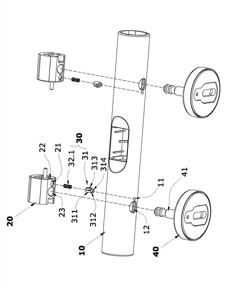
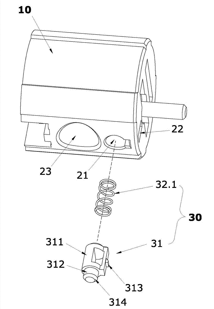
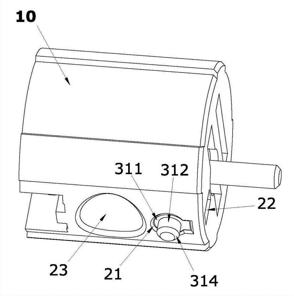
[0029] Such as figure 1 with Figure 4 A quick positioning device for a connecting shaft in a cover shaft sleeve shown includes a cover plate, a shaft sleeve 10 and a connecting shaft 20 that can be axially sleeved in the shaft sleeve 10, and a positioning device is provided in the radial direction of the shaft sleeve 10. Through hole 11, such as figure 2 with image 3 As shown, a mounting hole 21 is provided in the radial direction of the connecting shaft 20, and a spring pin device 30 is provided in the radial direction of the connecting shaft 20; the spring pin device 30 in this embodiment consists of a positioning pin 31 and a positioning pin 31 The pin 31 and the connecting shaft 20 are formed by an elastic member. The positioning pin 31 in this embodiment is formed by integrally forming a sliding post 311 and a plug pin 312. The diameter of the sliding post 311 is larger than the ap...

Example Embodiment

[0033] Example two (The positioning pin and the wave spring are integrally formed to form a spring pin device).

[0034] Such as Figure 5 with Image 6 A quick positioning device for a connecting shaft in a cover plate bushing shown in this embodiment is different from the first embodiment in that the elastic member uses a wave spring 32.2 instead of the compression spring 32.1 in the first embodiment. The wave spring 32.2 and the positioning pin 31 are integrally molded by injection molding, which makes it easier to assemble the spring pin device 30 in the mounting hole of the connecting shaft 20. Other structures, working principles, and specific implementation actions of this embodiment are the same as those in the first embodiment.

Example Embodiment

[0035] Example three (The elastic pin device composed of the positioning pin and the elastic arm is integrated with the connecting shaft).

[0036] Such as Figure 7 with Figure 8 This embodiment shows a quick positioning device for the connecting shaft in the cover plate sleeve. The difference between this embodiment and the first embodiment is that the elastic pin device 30 consists of a positioning pin 31 and a pin connected to the positioning 31 and the connecting shaft The elastic arm 32.3 between 20 is formed, and one end of the elastic arm 32.3 is fixed to the connecting shaft 20, and the other end is fixed to the positioning pin 31. The positioning pin 31, the elastic arm 32.3 and the connecting shaft 20 are integrally formed by injection molding, eliminating the need for installation in the first embodiment. Hole 21, limit sliding hole 22, sliding column 311 and the limit block 313 on its side; insert the connecting shaft 20 with the elastic pin device 30 in the axial d...


PUM


Abstract

The invention discloses a quick positioning device of a connecting shaft in a cover plate shaft sleeve. The quick positioning device comprises a cover plate shaft sleeve and a connecting shaft sleeved in the shaft sleeve, wherein a positioning through hole is arranged in a radial direction of the shaft sleeve; an elastic pin device is arranged in the radial direction of the connecting shaft; the elastic pin device consists of a positioning pin and an elastic piece connected between the positioning pin and the connecting shaft; the positioning pin is elastically plugged and buckled with the positioning through hole. In the process of sleeving the shaft sleeve axially, the positioning pin automatically ejects and is inserted into the positioning through hole when the positioning pin is aligned with the positioning through hole, so that the connecting shaft cannot axially slide in the shaft sleeve. When the connecting shaft needs be taken out from the shaft sleeve, the positioning pin is pressed to retract by the positioning through hole, so that the positioning pin and the positioning through hole are staggered to take out the connecting shaft quickly. Compared with the positioning structure of current cover plate shaft sleeve and connecting shaft, the positioning and connecting structure provided by the invention is simpler, more rapid and reliable in positioning and connection as well as detachment and separation of the shaft sleeve and the connecting shaft, and lower in manufacturing cost.

Description

technical field [0001] The invention relates to a quick-installation and positioning device for parts in a shaft sleeve at the rear end of a bathroom toilet cover, in particular to a quick positioning device for a connecting shaft in a cover shaft sleeve. Background technique [0002] The main positioning and connection methods of the connecting shaft in the shaft sleeve at the rear end of the existing toilet cover are: ① As disclosed in the Chinese utility model patent (CN201213769) for the installation structure of the slow-falling toilet cover, the 3 sets of mounting holes of the shaft sleeve 1.1 are provided with The connecting shaft 5 is provided with an annular groove 5.1, and the shaft sleeve 1.1 is provided with a bayonet 1.2 corresponding to the annular groove 5.1, and a lock 6 is engaged in the bay 1.2, and the end of the lock 6 is in the In the ring groove 5.1, the connecting shaft 5 is positioned and connected in the sleeve 1.1; this connection method needs to ma...

Claims


Application Information

Patent Timeline
IPC IPC(8): A47K13/26
Inventor 洪狄意谢伟泉王兵
Owner XIAMEN R&T PLUMBING TECH
Why Eureka
Try Eureka