Superabrasive cutting element with enhanced durability and increased wear life and apparatus so equipped

a cutting element and superabrasive technology, applied in the direction of drill bits, earthwork drilling and mining, construction, etc., can solve the problems of pdc form showing cracks, catastrophic failure of diamond tables, etc., to prolong useful life, reduce the tendency to catastrophic spall, crack and break, and improve the effect of durability

Inactive Publication Date: 2001-03-20
BAKER HUGHES INC
View PDF20 Cites 185 Cited by
  • Summary
  • Abstract
  • Description
  • Claims
  • Application Information

AI Technical Summary

Benefits of technology

It is a consequent advantage of the invention that the cutter, for a given depth of cut and formation material being cut, has a substantially enhanced useful life in comparison to prior art PDC cutters due to a greatly reduced tendency to catastrophically spall, chip, crack and break. It has been found that the invented cutter in PDC form may tend to show some cracks after use, but the small cracks surprisingly do not develop into a catastrophic failure of the diamond table as typically occurs in prior art PDC cutters.
It is a feature of the invented cutter that a rake land is provided on the diamond table that is angled at about 10.degree. to about 80.degree. with respect to the line of the sidewall of the cutter (assuming the cutter has a sidewall parallel to the longitudinal axis of the cutter). This is the range of rake land angles that the inventors currently believe will yield a cutter that has the extended useful life and desirable performance characteristics found in the preferred embodiments of the invention.
It is an advantage of the invention that the invented cutter has increased strength and impact resistance compared to prior art cutters, while not degrading cutter performance, due to the presence of both a

Problems solved by technology

It has been found that the invented cutter in PDC form may tend to show some cracks after use, but the small cracks sur

Method used


Image

  • Superabrasive cutting element with enhanced durability and increased wear life and apparatus so equipped
  • Superabrasive cutting element with enhanced durability and increased wear life and apparatus so equipped
  • Superabrasive cutting element with enhanced durability and increased wear life and apparatus so equipped

Examples


Embodiment Construction

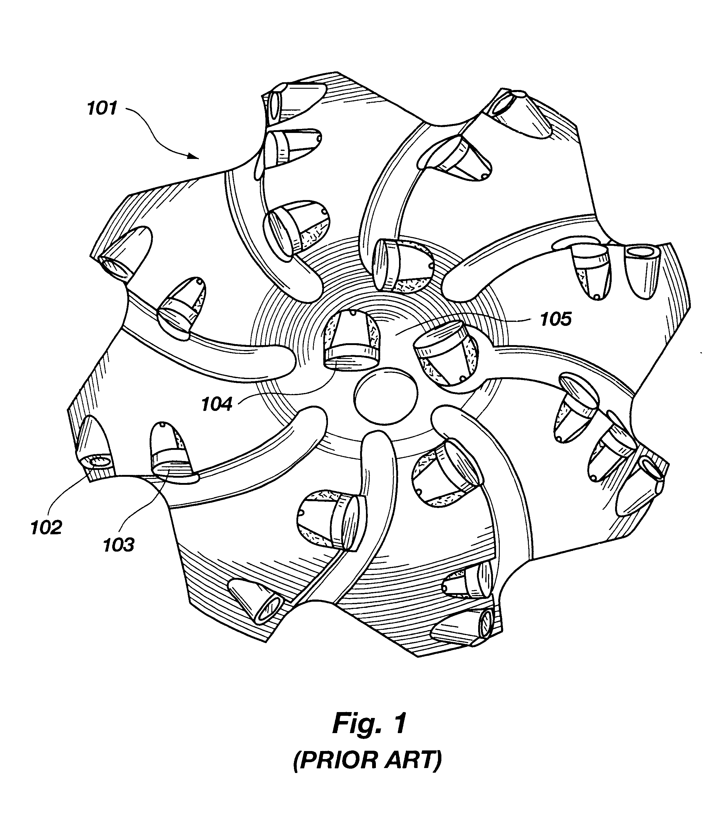
Referring to FIG. 1, an exemplary prior art drag bit is illustrated in distal end or face view. The drag bit 101 includes a plurality of cutters 102, 103 and 104 which may be arranged as shown in rows emanating generally radially from approximately the center of the bit 105. The inventors contemplate that the invented cutter will primarily be used on drag bits of any configuration.

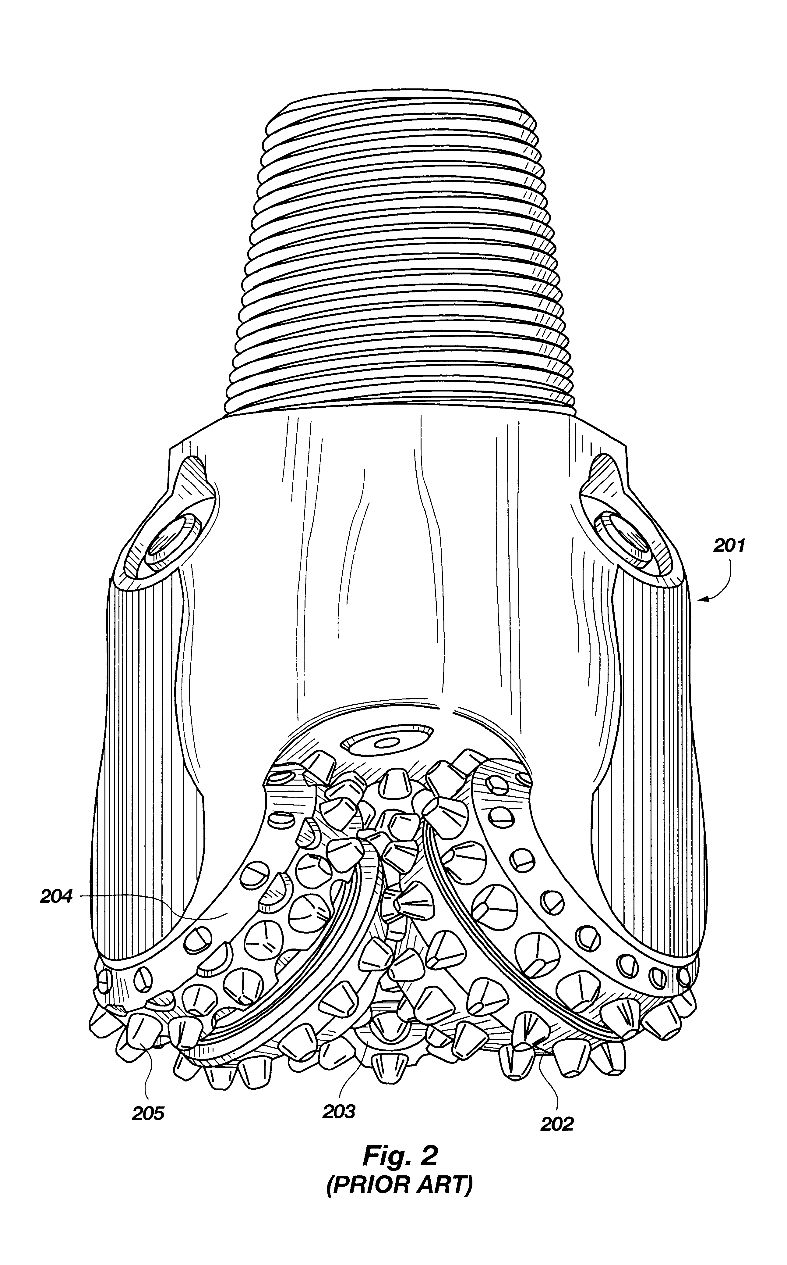
In FIG. 2, an exemplary prior art roller cone bit is illustrated in side view. The roller cone bit 201 includes three rotatable cones 202, 203 and 204, each of which carries a plurality of cone inserts 205. The inventors contemplate that the invented cutter will also be used on roller cone bits of various configurations in the capacity of cone inserts gage cutters and on wear pads.

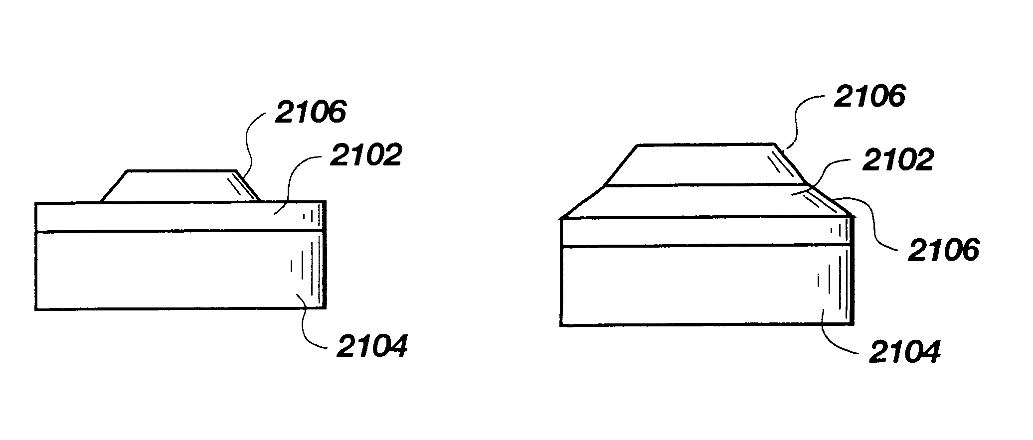
FIG. 3 depicts a side view of a prior art polycrystalline diamond cutter typically used in drag bits. The cutter 301 is cylindrical in shape and has a substrate 302, which is typically made of cemented carbide such as tungsten ca...


PUM


Abstract

A cutting element for use in drilling subterranean formations. The cutting element includes a superabrasive table mounted to a supporting substrate. The superabrasive table includes a two-dimensional cutting face having a cutting edge along at least a portion of its periphery, and a first surface extending forwardly and inwardly from a location radially interior of the cutting edge at a first angle of orientation with respect to the longitudinal axis of the cutting element. The cutting face also includes at least a second surface located between the first surface and the cutting edge and oriented at a different, greater angle to the longitudinal axis than the angle of orientation of the first surface.

Description

BACKGROUND OF THE INVENTION1. Field of the InventionThis invention relates to devices used in drilling and boring through subterranean formations. More particularly, this invention, relates to a polycrystalline diamond or other superabrasive cutter intended to be installed on a drill bit or other tool used for earth or rock boring, such as may occur in the drilling or enlarging of an oil, gas, geothermal or other subterranean borehole, and to bits and tools so equipped.2. State of the ArtThere are three types of bits which are generally used to drill through subterranean formations. These bit types are: (a) percussion bits (also called impact bits); (b) rolling cone bits, including tri-cone bits; and (c) drag bits or fixed cutter rotary bits (including core bits so configured), the majority of which currently employ diamond or other superabrasive cutters, polycrystalline diamond compact (PDC) cutters being most prevalent.In addition, there are other structures employed downhole, gen...

Claims


Application Information

Patent Timeline
IPC IPC(8): E21B10/46E21B10/56E21B10/567
CPCE21B10/5673
Inventor JUREWICZ, STEPHEN R.JENSEN, KENNETH M.TIBBITTS, GORDON A.
Owner BAKER HUGHES INC
Why Eureka
Try Eureka