[0019] In order to make the objectives, technical solutions, and advantages of the present invention clearer, the embodiments of the present invention will be described in further detail below in conjunction with the accompanying drawings.
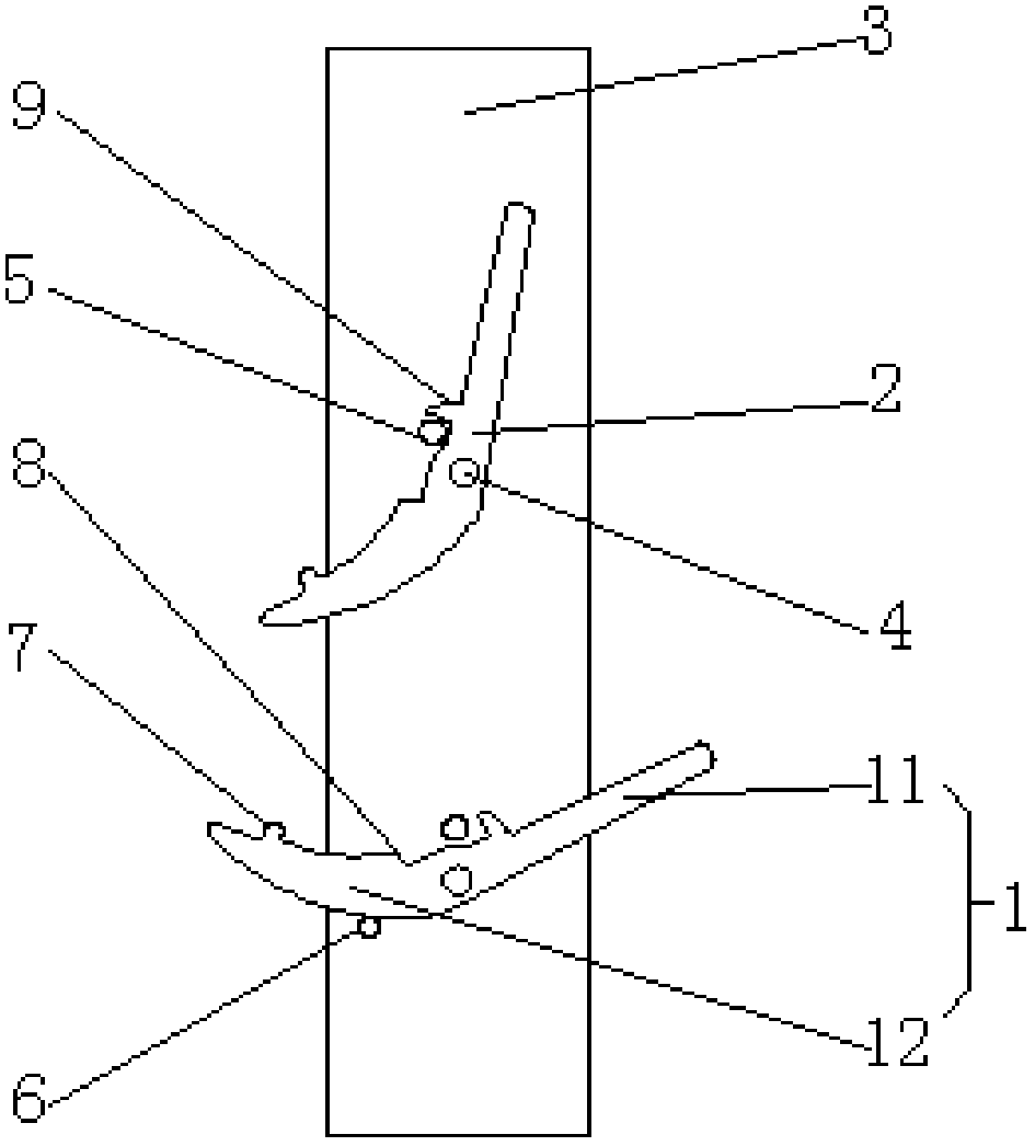
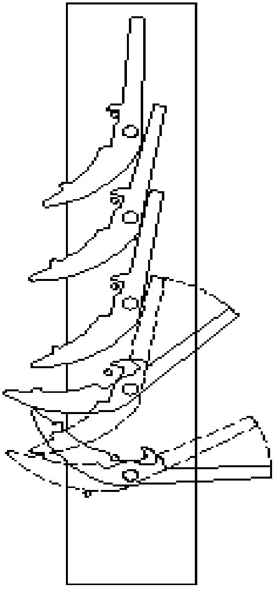
[0020] Such as figure 1 As shown, a stamping part placement device includes a swing rod, a bolt 4, a bracket 3, and a first limit pin 5. The swing rod is movably connected to the bracket 3 by the bolt 4, and the swing rod It includes a rod portion 11 and a counterweight portion 12. The counterweight portion 12 is heavier than the rod portion 11, the first limit pin 5 is arranged above the swing rod, and the first limit pin 5 is used for To limit the range of movement of the pendulum rod, the pendulum rod includes first to Nth pendulum rods from bottom to top, and N is greater than or equal to two. The pendulum rod, the bolt 4 and the first pendulum rod Each limit pin 5 has a one-to-one correspondence.
[0021] Among them, in this embodiment, the N pendulum rods include the first pendulum rod 1 and the second pendulum rod 2, the bolt 4 passes through the pendulum rod and the bracket 3 is connected by a nut, so that the pendulum rod is fixed with the bolt 4 , Capable of rotating movement at a certain angle. During production, the gap between the pendulum rod and the bracket 3 is adjusted by adjusting the tightness of the nut and the bolt 4, and when the gap is adjusted to an appropriate gap, the nut and the bolt 4 are welded to death.
[0022] Such as figure 1 As shown, by setting the first limit pin 5 above the pendulum rod, in the working state, when the pendulum rod rotates a certain angle clockwise, the counterweight 12 will be in close contact with the first limit pin 5, thereby preventing the pendulum rod from continuing Rotation, that is, the first limit pin 5 can automatically limit the rotation of the pendulum rod in the clockwise direction, without changing the weight of the weight part 12, any stamping parts of appropriate weight can be placed on the pendulum rod; 12 It only needs to be slightly heavier than the weight of the rod 11. In the non-working state, that is, when the rod 11 is not placed with stamping parts, since the weight of the counterweight 12 is heavier than the weight of the rod 11, the swing rod can automatically return to its position. , That is, the pendulum rod rotates counterclockwise back to the original position. At this time, the first limit pin 5 will contact the rod 11 to prevent the pendulum rod from continuing to rotate counterclockwise, so as to automatically limit the counterclockwise rotation direction of the pendulum rod. In actual operation, the structure of the present invention is light and simple, and easy to operate, reducing the damage to the stamping parts caused by manual placement, thereby improving the placement quality of the stamping parts, and also greatly improving work efficiency.
[0023] Specifically, as a preference, such as figure 1 As shown, the pendulum rods are arranged at equal intervals along the longitudinal direction of the support 3, and the rotational motion trajectory of any pendulum rod in the pendulum rod has an intersection with the rotational motion path of the previous pendulum rod. The pendulum rods are arranged in the longitudinal direction according to a certain interval, and the pendulum rods are aligned up and down, and the bolts 4 on each pendulum rod are in a straight line. This forms an automatic pendulum rod mechanism, and can adjust the pendulum during production according to the height of the stamping part The spacing between the rods. In this embodiment, the weight portion 12 of the first pendulum rod 1 can contact with the weight portion 12 of the second pendulum rod 2 after rotating and exert an upward force on it, that is, the upper and lower pendulum rods There is an intersection in the rotational motion trajectory.
[0024] More specifically, such as figure 1 As shown, the upper surface of the weight portion 12 of the pendulum rod is provided with a protrusion 7, and the protrusion 7 contacts the weight portion 12 of the previous pendulum rod by rotating and exerts a force. In this embodiment, the weight portion 12 of the first pendulum rod 1 is rotated to contact the weight portion 12 of the second pendulum rod 2 and exert an upward force, so that the second pendulum rod 2 also rotates to a certain angle In order to meet the requirements of placing stamping parts. A protrusion 7 is provided on the weight portion 12 of the first pendulum rod 1, so that the protrusion 7 and the weight portion 12 of the first pendulum rod 2 contact and exert a force. The protrusion 7 and the second pendulum rod When the counterweight portion 12 of the rod 2 contacts and acts, the acting area is relatively small, so the applied force is also relatively small, which is convenient for operation and at the same time controls the friction loss, which has obvious advantages in actual use.
[0025] Specifically, as a preference, the pendulum bar includes a groove 8 provided on the upper surface of the weight portion 12 of the pendulum bar. In the working state, the groove 8 is used to accommodate the first The limiting pin 5, the groove 8 and the first positioning pin 5 cooperate to limit the rotation of the pendulum rod in the clockwise direction. In the working state, the pendulum rod rotates clockwise to a certain angle to meet the requirements of use. A groove 8 is provided on the counterweight 12 so that the first limit pin 5 is stuck in the groove 8 to prevent the pendulum rod from continuing clockwise. Rotation means to limit the rotation of the pendulum rod in a clockwise direction, and at the same time avoids the phenomenon that the first restricting pin 5 slides on the counterweight 12 and causes the pendulum rod to be unstable.
[0026] As a preference, such as figure 1 As shown, the swing lever further includes a chuck 9 which is arranged on the rod portion 11 of the swing lever. In the non-working state, the chuck 9 passes through and the first limit pin 5 Cooperate to limit the counterclockwise rotation of the pendulum rod. In the non-working state, the chuck 9 is just stuck on the first limit pin 5, so that the pendulum rod cannot rotate counterclockwise, which is to limit the counterclockwise rotation direction of the pendulum rod
[0027] As a preference, such as figure 1 As shown, a second limit pin 6 is further provided under the first swing lever 1, and the second limit pin 6 is used to limit the counterclockwise rotation direction of the first swing lever 1. Rotate the first pendulum rod 1 clockwise to a certain angle until it just touches the second pendulum rod 2. At this time, a second limit pin 6 is set closely below the first pendulum rod 1 to prevent the first pendulum rod 1 Rotate counterclockwise. At this time, the rod 11 of the first pendulum rod 1 is close to the level. The protrusion of the rod 11 avoids manually rotating the first pendulum rod 1 again, and the stamping can be directly placed on the rod. Relative to the first limit pin 5, the first pendulum rod 1 can also rotate a certain angle clockwise to contact the first limit pin 5. At this time, the gravity of the stamping part on the rod 11 That is, the first swing rod 1 can continue to rotate clockwise until it contacts the first limit pin 5, and finally stops rotating.
[0028] Further, as a preference, the thickness of the pendulum rod is 10 mm, and the pendulum rod is processed by a casting or wire cutting process. The thickness of the pendulum rod of 10mm enables the pendulum rods to be in better contact and function.
[0029] Such as figure 2 As shown, in actual use, due to the limit restriction of the second limit pin 6, the rod portion 11 of the first swing rod 1 has already approached horizontal, making the rod portion 11 protrude. When working, The first stamping part can be placed directly on the first pendulum rod 1. The first pendulum rod 1 is affected by the gravity of the stamping part, so that the counterweight part 12 of the pendulum rod moves upward, which affects the second pendulum rod 2. The counterweight 12 acts and makes it make a clockwise rotation. The second swing rod 2 will eventually make the rod 11 protrude, and the second stamping part can be placed directly. Repeat the above-mentioned movement process to form a domino The domino effect realizes the purpose of automation of the pendulum. When the pendulum is not working, the stamping parts are removed. Because the counterweight 12 of the pendulum is heavier than the rod 11, the pendulum can realize the function of the return of the pendulum, that is, the pendulum rotates back counterclockwise. In the original position, with the first positioning pin, the second positioning pin and the chuck, the pendulum rod rotates counterclockwise to the original position and stops, achieving the function of return positioning.
[0030] The sequence numbers of the foregoing embodiments of the present invention are only for description, and do not represent the superiority of the embodiments.
[0031] The above descriptions are only preferred embodiments of the present invention and are not intended to limit the present invention. Any modification, equivalent replacement, improvement, etc. made within the spirit and principle of the present invention shall be included in the protection of the present invention. Within range.