Fall-preventing brake sliding carriage and fall-preventing brake method for hoist bucket of vertical shaft

A technology of anti-falling and hanging buckets, which is applied in the field of guidance and anti-falling of hoisting buckets in construction shafts, and in the field of vertical lifting container guidance and anti-falling. Grasp the lifting of the wire rope and other issues to achieve the effect of avoiding secondary arrest, good anti-falling effect, and improving safety and reliability

Inactive Publication Date: 2014-04-16
CHINA UNIV OF MINING & TECH
View PDF6 Cites 0 Cited by
  • Summary
  • Abstract
  • Description
  • Claims
  • Application Information

AI Technical Summary

Problems solved by technology

However, the existing carriage device can only provide guiding function for the bucket, and cannot provide anti-drop protection for the bucket when the lifting wire rope breaks.
The existing bucket anti-fall device is to improve the sliding frame so that the sliding frame can provide the guiding and anti-falling functions for the bucket at the same time, but this type of sliding frame uses spring force to compress the lifting wire rope. , the slide frame cannot effectively grasp the hoisting wire rope, and when the weight of the hanging bucket below is relatively large, effective anti-fall protection cannot be guaranteed

Method used


Image

  • Fall-preventing brake sliding carriage and fall-preventing brake method for hoist bucket of vertical shaft
  • Fall-preventing brake sliding carriage and fall-preventing brake method for hoist bucket of vertical shaft
  • Fall-preventing brake sliding carriage and fall-preventing brake method for hoist bucket of vertical shaft

Examples


Embodiment Construction

[0022] An embodiment of the present invention will be further described below in conjunction with accompanying drawing:

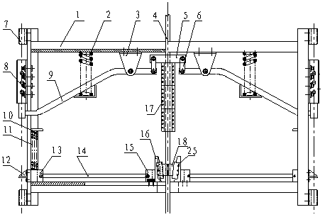
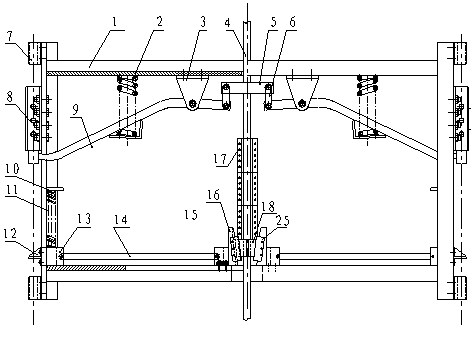
[0023] exist figure 1 , 2 Among them, the vertical shaft hoisting bucket anti-fall braking carriage includes a top beam 1-1, a bottom beam 1-3 set on the hoisting wire rope 4, and longitudinal beams fixed on both sides of the top beam 1-1 and the bottom beam 1-3. Frame body 1 composed of 1-2; the wire rope 4 between the top beam 1-1 and the bottom beam 1-3 is sequentially provided with a connecting block 5 and three rope clips 17 clamped by bolts and lifting wire rope 4, both sides The upper and lower sides of the longitudinal beam 1-2 are respectively provided with the guide sleeve 7 of the suit stabilization rope 27, and the upper part of the longitudinal beam 1-2 on both sides is equipped with anti-falling catch pliers 8 symmetrically by bolts, and the lower part of the longitudinal beam 1-2 on both sides The vertical slider guide groove 26 is symmetri...


PUM


Abstract

The invention discloses a fall-preventing brake sliding carriage and a fall-preventing brake method for a hoist bucket of a vertical shaft. The fall-preventing brake sliding carriage comprises a carriage body sleeved on a hoist steel wire rope, two springs and support seats which are symmetrically fixed on a top beam of the carriage body, levers hinged with the support seats, connecting plates connected with the upper parts of the levers, connecting blocks hinged with the connecting plates, four guide sleeves which are symmetrically fixed on longitudinal beams at two sides of the carriage body and sleeved on stable ropes, two fall-preventing catch forceps which are symmetrically fixed on the longitudinal beams at two sides of the carriage body as well as a self-locking mechanism. When the hoist steel wire rope is broken above the sliding carriage, the hoist bucket quickly falls off and a rope cappel downwards slides into a lower sliding wedge along with the downwards-moving hoist steel wire rope to drive the sliding wedge to downwards move; the hoist steel wire rope is clamped by the self-locking mechanism on the sliding carriage; the sliding carriage is clamped on the stable ropes by the fall-preventing catch forceps; and the hoist bucket of the hoist steel wire rope is prevented from falling and is protected. The sliding carriage can be used for guiding for the hoist bucket and also has the functions of fall-preventing protection, automatic combination and separation from the hoist steel wire rope and the like. The sliding carriage is simple in structure and favorable in fall-preventing effect.

Description

technical field [0001] The invention relates to an anti-fall braking carriage and anti-fall braking method for a vertical shaft hoisting bucket, and is especially suitable for guiding and anti-falling of a hoisting bucket in a construction shaft, and also for guiding and anti-falling of a rope-guided vertical hoisting container. Background technique [0002] At present, in most shaft construction projects, buckets are used as the gangue discharge device for construction. The bucket is suspended by a wire rope and runs up and down in the shaft of the shaft. In order to prevent the bucket from sloshing during its operation in the shaft, a slide frame is usually used as a guide for the bucket. But the existing carriage device can only provide guiding function for the bucket, and cannot provide anti-falling protection for the bucket when the lifting wire rope breaks. The existing bucket anti-fall device is to improve the sliding frame so that the sliding frame can provide the ...

Claims


Application Information

Patent Timeline
Patent Type & Authority Patents(China)
IPC IPC(8): B66B5/24
Inventor 曹国华朱真才王彦栋李伟周公博彭玉兴张磊
Owner CHINA UNIV OF MINING & TECH
Why Eureka
Try Eureka