Numerical control particle glass cutting machine

A glass cutting and cutting machine technology, applied in the direction of glass cutting devices, glass production, glass manufacturing equipment, etc., can solve the problems of low production efficiency, affecting production efficiency, and not too much impact, so as to achieve improved production efficiency and significant production efficiency , Good product quality

Inactive Publication Date: 2012-10-03
苏家亮
View PDF3 Cites 11 Cited by
  • Summary
  • Abstract
  • Description
  • Claims
  • Application Information

AI Technical Summary

Problems solved by technology

[0002] At present, the glass cutting machine used for cutting flat glass on the market, in terms of technology, the most efficient is to use a glass cutting table to draw lines on the glass surface, and then manually break the glass from the cutting line. There is a fatal defect in the glass cut by the process, that is, the cutting section of the glass is uneven, which has little impact on industries that do not require high cross-s

Method used


Image

  • Numerical control particle glass cutting machine
  • Numerical control particle glass cutting machine
  • Numerical control particle glass cutting machine

Examples


Embodiment Construction

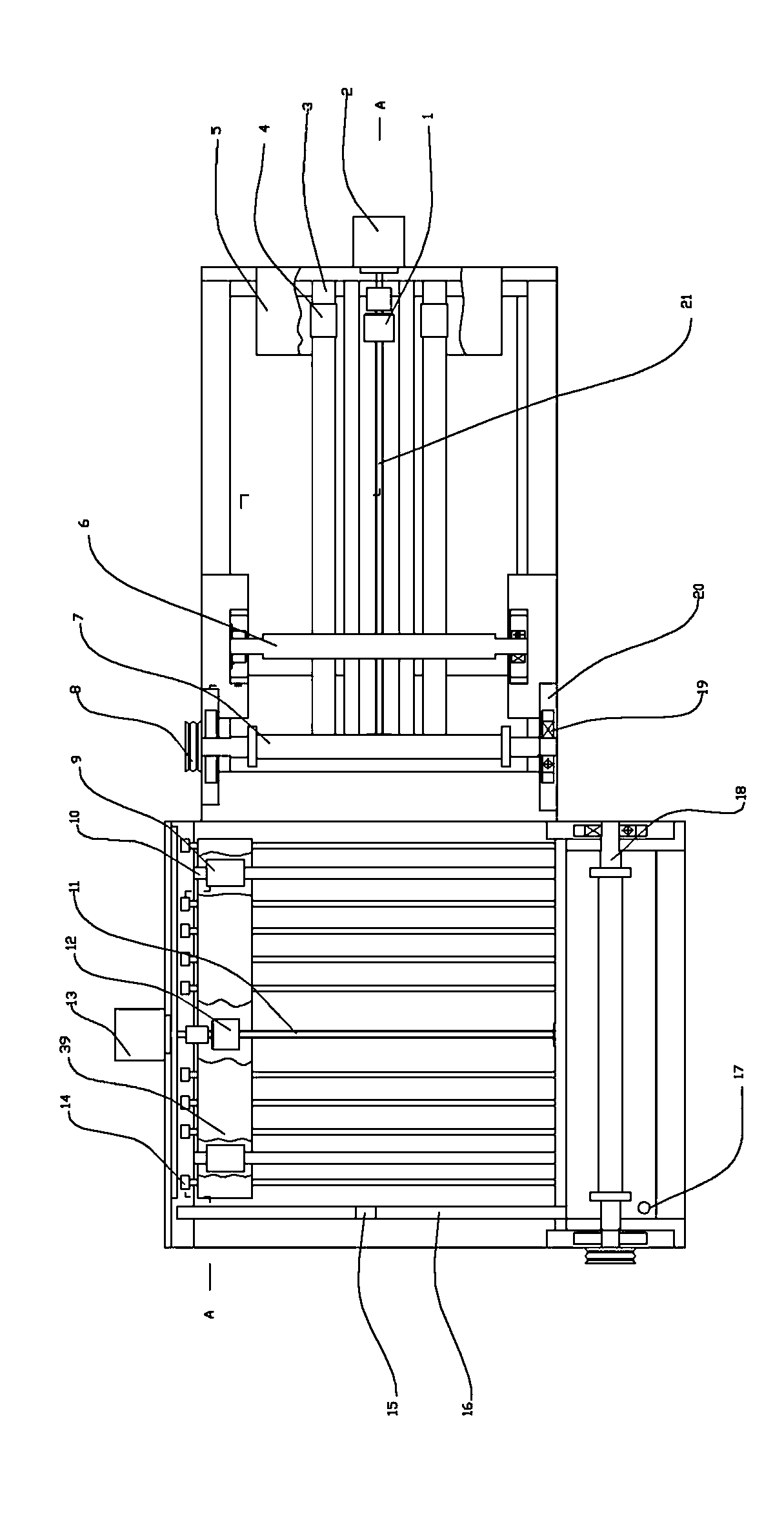
[0022] In the numerical control particle glass cutting machine provided by the present invention, the numerical control part is controlled by a programmable logic controller PLC, and the mechanical part includes an X-direction cutting mechanism and a Y-direction cutting mechanism. The X-direction cutting mechanism first cuts flat glass into strip-shaped glass strips , the Y-direction cutting mechanism further cuts the glass strips into granules. Such as figure 1 , figure 2 As shown, the X-direction cutting mechanism includes an X-direction workbench 22 supported by an X-direction frame. The middle part of the X-direction workbench 22 is provided with a horizontal guide groove 32 that penetrates up and down. An X-direction feeding stepper motor 2 is installed on the rack, and the output end of the X-direction feeding stepper motor 2 is matched with an X-direction ball screw 21 in the same direction as the transverse guide groove 32, and the X-direction ball screw 21 is The n...


PUM


Abstract

The invention discloses a numerical control particle glass cutting machine. The numerical control particle glass cutting machine comprises an X-direction cutting mechanism and a Y-direction cutting mechanism which are controlled by a programmable logic controller (PLC), wherein a glass sheet is transmitted to a cutting device by a transmission device for cutting; the cutting device consists of a knife flywheel shaft and a plurality of groups of disc knife flywheels which are sleeved in the axial direction of the knife flywheel shaft in parallel and at intervals; and the glass sheet is cut into strips and then is cut into particles. By the numerical control particle glass cutting machine, the line-marking and sheet-breaking process of the traditional flat glass cutting machine is changed; the plurality of disc knife flywheels are arranged on the knife flywheel shaft in the X direction and the Y direction in parallel and are driven by the external power along the knife flywheel shaft to rotate, and the rotating knife flywheels directly cut off the flat glass, so the sheet-breaking procedure is saved; carborundum is distributed on two sides of the cutting edges of the disc knife flywheels, so that the cutting section of the glass is smooth and flat like that of the ground glass, so the edging process is saved and three procedures are finished at one step; in addition, tens of, even hundreds of knife flywheels can be assembled on the knife flywheel shaft to work, so the production efficiency is improved obviously.

Description

technical field [0001] The invention relates to the field of glass cutting equipment, in particular to a glass cutting machine for cutting rectangular and square flat glass particles, especially suitable for cutting small-sized micro particles. Background technique [0002] At present, the glass cutting machine used for cutting flat glass on the market, in terms of technology, the most efficient is to use a glass cutting table to draw lines on the glass surface, and then manually break the glass from the cutting line. There is a fatal defect in the glass cut by the process, that is, the cutting section of the glass is uneven, which has little impact on industries that do not require high cross-section smoothness and flatness, but for industries that require high cross-section smoothness and flatness, it is necessary to increase The section edging process is time-consuming and labor-intensive, which affects production efficiency, especially for small-sized micro-particles, th...

Claims


Application Information

Patent Timeline
IPC IPC(8): C03B33/023
CPCY02P40/57
Inventor 苏家亮
Owner 苏家亮
Why Eureka
Try Eureka