
Drill chuck with two halves of split nuts with smooth engagement planes and manufacturing method of split nuts

A technology for splicing nuts and manufacturing methods, which is applied in the directions of nuts, manufacturing tools, connecting components, etc., can solve problems such as affecting the quality of drill chucks, not being well butted, affecting the quality of butting, etc., to improve flexibility and transmission efficiency. , The effect of eliminating the breaking process and simplifying the assembly process

Inactive Publication Date: 2012-06-20
CHANGZHI HUIFENG ELECTROMECHANICAL INDAL TRADE
View PDF0 Cites 0 Cited by
  • Summary
  • Abstract
  • Description
  • Claims
  • Application Information

AI Technical Summary

Problems solved by technology

Therefore, there are very high requirements for the knocked section, and there should be no tearing when knocked off, otherwise, it will not fit well after assembly.
Even if there is no tearing phenomenon, due to the influence of the impact force when breaking, the broken surface often has a slight deformation, which also affects the fit quality after assembly, especially the fit quality of the inner taper thread of the nut.
The gap caused by the poor matching quality will make the meshing transmission between the inner taper thread of the nut and the threaded section of the jaw not good, and it is easy to produce abnormal noise, which will affect the flexibility of the drill chuck in severe cases.
Therefore, the nut of the drill chuck is manufactured in one piece, and then broken and assembled will cause a series of problems that affect the quality of the drill chuck

Method used


Image

  • Drill chuck with two halves of split nuts with smooth engagement planes and manufacturing method of split nuts
  • Drill chuck with two halves of split nuts with smooth engagement planes and manufacturing method of split nuts
  • Drill chuck with two halves of split nuts with smooth engagement planes and manufacturing method of split nuts

Examples


Embodiment Construction

[0060] The specific implementation manner of the present invention will be described in detail below by means of drawings and examples.

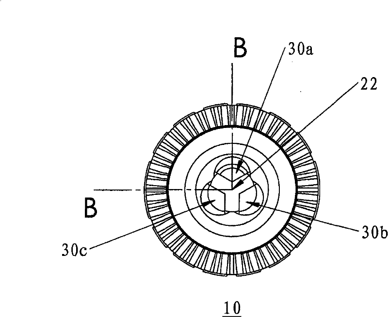
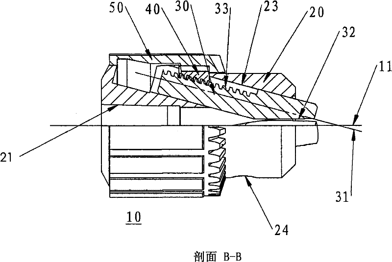
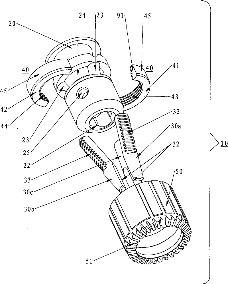
[0061] Take Figure 1 and figure 2 The drill chuck shown serves as a basis for illustrating the invention, Figures 1 and figure 2It is only an embodiment of a typical drill chuck, and the technical solution of the present invention will be embodied in the structure of the embodiment. The drill chuck can be improved according to the invention, that is, the invention is not limited to the embodiment of the drill chuck, and the solution of the invention can also be applied to drill chucks with or without keys of various existing designs. The following detailed descriptions are only carried out through examples, and are not meant to limit the protection scope of the present invention.

[0062] Figure 1, figure 2 , Figure 3C and Figure 3D As shown, the present invention provides a drill chuck 10 with two halves of a split nut with a smoo...


PUM


Abstract

The invention relates to a drill chuck with two halves of split nuts with smooth engagement planes, which comprises a body with a longitudinal axial line, three gripping jaws are respectively arranged in three inclined holes which are arranged on the body with the uniform interval of 120 degrees, the two halves of the split nuts are rotatably arranged in a middle groove of the body and further matched with thread sections on the three gripping jaws for forming a thread transmission mechanism, a gear ring is fixed on the outer edge of the two halves of the split nuts by interference press fit,the two halves of the split nuts are combined into a whole, and the drill chuck is characterized in that the splicing engagement surfaces of the two halves of the split nuts are the smooth planes with the surface roughness Ra of not more than 1.6 mu m, and the planeness of not more than 0.8 mu m. The invention simultaneously relates to a manufacturing method of the two halves of the split nuts with the smooth engagement planes. The invention can simplify the assembly process steps, avoid the knocking-off of the nuts before the assembly, greatly reduce the cost of materials and improve the flexibility and the transmission efficiency of the drill chuck using the two halves of the split nuts.

Description

technical field [0001] The present invention relates to a drill chuck for clamping rotary tools, and more particularly, to a drill chuck having two halves of a split nut with smooth engaging planes and a method of manufacturing the split nut. Background technique [0002] The drill chuck is a clamping device widely used for rotating tools, for example, for clamping tools such as drills, reamers, and taps. A variety of drill chucks have been developed in this technical field. A very common drill chuck includes a body with a longitudinal axis, and three jaws are respectively arranged in three inclined holes uniformly distributed at intervals of 120 degrees on the body. , a two-half split nut is rotatably placed in the middle groove of the body, and cooperates with the threaded segments on the three jaws to form a thread transmission mechanism, and a ring gear is fixed on the outer diameter of the two halves of the split nut by interference press fit up and unite them. Thus, ...

Claims


Application Information

Patent Timeline
Patent Type & Authority Patents(China)
IPC IPC(8): B25B29/00F16B37/08
Inventor 李勇怀田先明苏立航马莉韩彦斌高斌
Owner CHANGZHI HUIFENG ELECTROMECHANICAL INDAL TRADE
Learn More