Eureka AIR delivers breakthrough ideas for toughest innovation challenges, trusted by R&D personnel around the world.
Anti-theft lock
What is Al technical title?
Al technical title is built by PatSnap Al team. It summarizes the technical point description of the patent document.
A technology of anti-theft locks and lock cylinders, applied in the field of anti-theft locks, can solve the problems of complex structure and poor anti-theft effect of tumbler locks, and achieve good social and economic benefits, low cost and simple structure
Inactive Publication Date: 2014-09-03
平顶山市鼎福锁业科技有限公司
View PDF3 Cites 1 Cited by
Summary
Abstract
Description
Claims
Application Information
AI Technical Summary
This helps you quickly interpret patents by identifying the three key elements:
Problems solved by technology
Method used
Benefits of technology
Problems solved by technology
[0003] In view of the above situation, in order to overcome the defects of the prior art, the object of the present invention is to provide an anti-theft lock, which can effectively solve the problems of complex structure and poor anti-theft effect of the tumbler lock.
Method used
Image
Click on the blue label to locate the original text in one second.
Reading with bidirectional positioning of images and text.
Examples
Embodiment Construction
[0014] The specific implementation manners of the present invention will be described in further detail below in conjunction with the accompanying drawings.
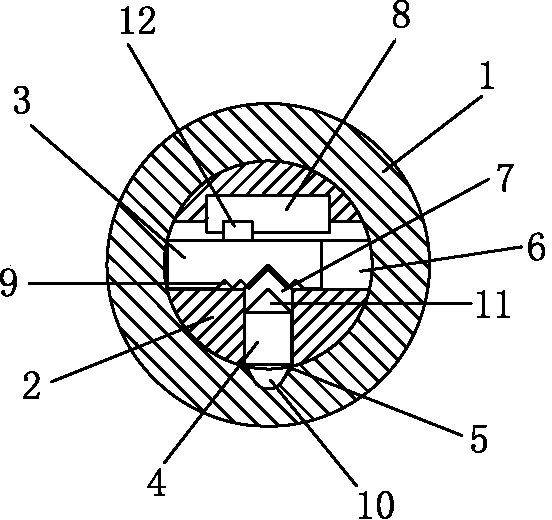
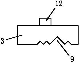
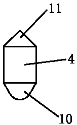
[0015] Depend on Figure 1-Figure 8 Given, including the lock body and the lock core, the lock core 2 is installed in the center of the lock body 1, the inner wall of the lower part of the lock body 1 has a moving bead brake hole 5, the center of the lock core 2 has a first moving bead hole 6 in the transverse direction, and the lock core 2 The lower part has a second moving bead hole 7 connected with the first moving bead hole 6, the center line of the first moving bead hole 6 is perpendicular to the center line of the second moving bead hole 7, and the upper part of the lock cylinder 2 has a Above the moving bead hole 6, and the key hole 8 connected with the first moving bead hole 6, the first moving bead hole 6 is equipped with a first moving bead 3 that can move left and right, and the first moving bead 3 top has a k...
PUM
Abstract
The invention relates to an anti-theft lock, which can be used for effectively solving the problems of complicated structure and poor anti-theft effect of a pin tumbler lock. The technical scheme adopted by the invention is as follows: the anti-theft lock comprises a lock body and a lock core, the lock core is mounted in the center of the lock body, a moving ball braking hole is formed in the internal wall of the lower part of the lock body, first moving ball holes are formed in the center of the lock core in the transverse direction, second moving ball holes communicated with the first moving ball holes are formed in the lower part of the lock core, the center line of the first moving ball holes is vertical to that of the second moving ball holes, a keyhole, which is located above the first moving ball holes and is communicated with the first moving ball holes, is formed in the upper part of the lock core, first moving balls, which can move leftwards and rightwards, are mounted in the first moving ball holes, a cylindrical bulged part, which extends into the keyhole, is arranged at the upper part of each first moving ball hole, the lower part of each first moving ball hole is provided with a plurality of clamping grooves, and second moving balls, which can move upwards and downwards, are mounted in the second moving ball holes. The anti-theft lock has the advantages of novel, unique and simple structure, easiness in operation, strong anti-theft function and low cost, and accordingly has excellent social and economic benefits.
Description
technical field [0001] The invention relates to a lock, in particular to an anti-theft lock. Background technique [0002] Locks are common anti-theft tools. The tumbler lock is widely used because of its simple structure and practicality. The structure of the pin lock is roughly the same, that is, a group of cylindrical pins are installed in the pin hole of the lock cylinder, and the key has a corresponding depth of teeth. The method of unlocking is roughly the same, that is, move the corresponding pins up and down according to the different heights of the key teeth, so that the height of each lock pin pin is at the interface between the lock shell and the lock core, and then rotate the key to drive the lock. Core, to achieve the purpose of unlocking. This type of lock is located in the shifting tooth channel. Without touching the pin, foreign matter can easily enter the inner end of the keyhole, and various unlocking tools can be inserted through the shifting tooth chan...
Claims
Application Information
Patent Timeline
Application Date:The date an application was filed.
Publication Date:The date a patent or application was officially published.
First Publication Date:The earliest publication date of a patent with the same application number.
Issue Date:Publication date of the patent grant document.
PCT Entry Date:The Entry date of PCT National Phase.
Estimated Expiry Date:The statutory expiry date of a patent right according to the Patent Law, and it is the longest term of protection that the patent right can achieve without the termination of the patent right due to other reasons(Term extension factor has been taken into account ).
Invalid Date:Actual expiry date is based on effective date or publication date of legal transaction data of invalid patent.