Gear case for high-power vertical roller mill

A vertical roller mill, high-power technology, applied in the direction of belt/chain/gear, mechanical equipment, transmission device, etc., can solve the problem of small transmission torque, poor load transmission capacity, and poor load equalization capacity of vertical roller mill gearboxes and other problems to achieve the effect of improving the ability to transmit power and load and improving the load-sharing capacity

Inactive Publication Date: 2012-10-03
宝钢苏冶重工有限公司
View PDF6 Cites 6 Cited by
  • Summary
  • Abstract
  • Description
  • Claims
  • Application Information

AI Technical Summary

Problems solved by technology

In this three-stage transmission structure, because the second-stage parallel shaft gear transmission adopts a pair of cylindrical gear meshing transmission structure, it has the following disadvantages: 1. The ability to transmit load is poor (transmission torque is small), and the efficiency of power transmission is low. And the weight is heavy; 2. The transmission speed ratio is low, generally the transmission speed ratio is less than 4.5
Therefore, generally speaking, the vertical roller mill gearbox disclosed in Comparative Document 1 has poor load sharing capacity and cannot meet the load sharing capacity requirements of high-power gearboxes.
[0006] To sum up, the three-stage transmission structure of the vertical roller mill gearbox disclosed in Comparative Document 1 is not suitable for a vertical roller mill gearbox with a transmission power of more than 3500kW, a transmission ratio of more than 4.5, a high power, a large transmission ratio, and a strong load-sharing capacity. Roller mill gearbox

Method used


Image

  • Gear case for high-power vertical roller mill
  • Gear case for high-power vertical roller mill
  • Gear case for high-power vertical roller mill

Examples


Embodiment 1

[0027] Example 1: A high-power vertical roller mill gearbox

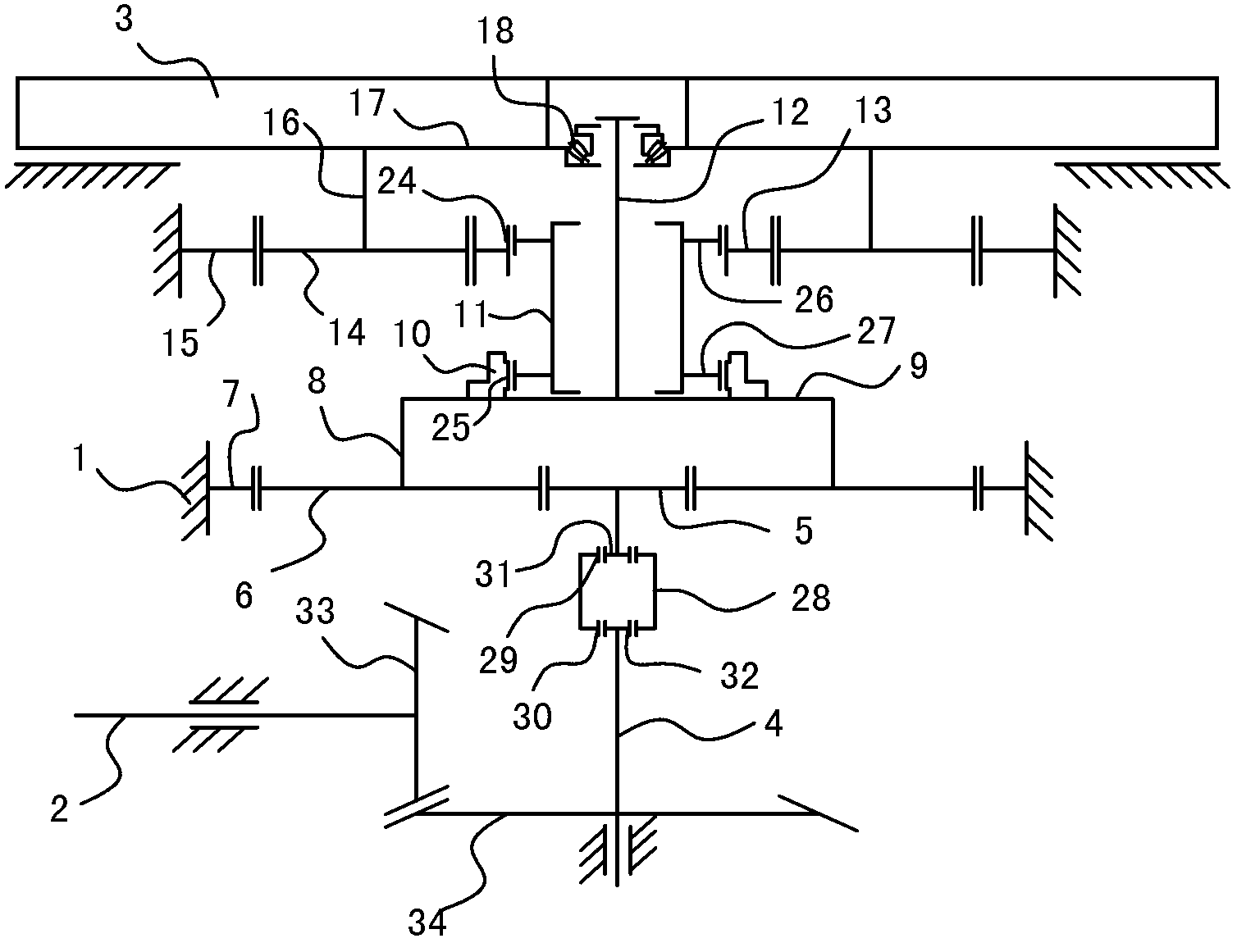
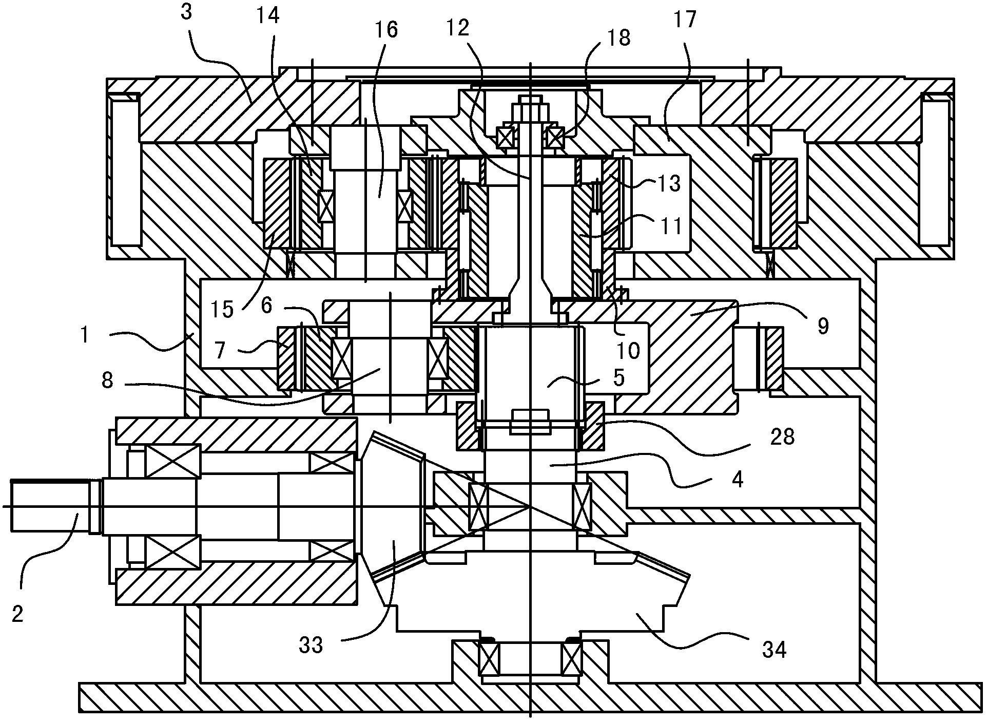
[0028] like figure 2 and image 3As shown, the gear box of the vertical roller mill is composed of a box body 1, an input shaft 2, an output flange 3 and a three-stage reduction transmission structure arranged in the box body 1. Wherein, the input shaft 2 is arranged at the side of the box body 1 , and the output flange 3 is arranged at the top of the box body 1 . The three-stage deceleration transmission structure is composed of the first-stage transmission mechanism, the second-stage transmission mechanism and the third-stage transmission mechanism. The first-stage transmission mechanism, the second-stage transmission mechanism and the third-stage transmission mechanism are in the box 1 is arranged in order from bottom to top.

[0029] Compare below figure 2 with image 3 Describe the three-stage reduction transmission structure respectively:

[0030] The first-stage transmission mechanism adopts a bevel g...

Embodiment 2

[0033] Example 2: A high-power vertical roller mill gearbox

[0034] The difference from Embodiment 1 is that the first-stage transmission mechanism in Embodiment 1 is changed from a bevel gear mechanism to a pulley mechanism, and the pulley mechanism is composed of a transmission belt and a pair of pulleys connected. Bottom of body 1 (not shown). Other structures are the same as those in Embodiment 1, and will not be described again here. Variations in this embodiment can also achieve the purpose of the present invention and obtain the same or similar technical effects.

Embodiment 3

[0035] Example 3: A high-power vertical roller mill gearbox


PUM


Abstract

The invention discloses a gear case for a high-power vertical roller mill, which is composed of a three-stage reduction transmission structure. The gear case for the high-power vertical roller mill is characterized in that a first stage transmission mechanism adopts a bevel gear or a belt pulley or a worm gear mechanism, and a second stage transmission mechanism and a third stage transmission mechanism adopt a planet gear mechanism. The three stages of transmission mechanisms are sequentially arranged from bottom to top inside a case body; an input shaft of the first stage transmission mechanism is used as an input end; an output shaft of the first stage transmission mechanism is in transmission connection with a sun wheel of the second stage transmission mechanism, and an inner gear of the second stage transmission mechanism is fixed. On one hand, the planet gear of the second stage transmission mechanism is in transmission connection with the sun wheel of the third stage transmission mechanism through an inner gear sleeve and a duplex outer gear sleeve, on the other hand, the planet gear of the second stage transmission mechanism is supported on a planet carrier of the third stage transmission mechanism through a hanger rod and a thrust bearing via floating suspension, and the planet carrier of the third stage transmission mechanism is fixedly connected with an output flange. The invention provides the gear case for the high-property vertical roller mill with high power, large transmission ratio and strong uniform loading capacity.

Description

technical field [0001] The invention relates to large-scale grinding equipment used in industries such as cement, electric power, metallurgy, chemical industry, non-metallic mines, etc., and particularly relates to the structure of a gearbox (reducer) used for power transmission in a vertical roller mill. Background technique [0002] Vertical roller mill, referred to as vertical mill, is a large-scale grinding equipment that grinds block, granular and powdery raw materials into powdery materials. It is widely used in cement, electric power, metallurgy, chemical industry, non-metallic minerals and other industries. For example, it is used to grind raw meal and clinker in the cement industry, to grind slag in the metallurgical industry, to grind coal powder in the thermal power generation industry, and so on. [0003] see figure 1 As shown, the vertical roller mill is mainly composed of grinding roller 19, grinding disc 20, gearbox 21 (reducer), motor 22 and body 23, among w...

Claims


Application Information

Patent Timeline
IPC IPC(8): F16H37/02
Inventor 万中福刘可蒋安毅王庭尧徐小波张跃钢
Owner 宝钢苏冶重工有限公司
Why Eureka
Try Eureka