Lower path demultiplexing filter based on wave guide type photon crystal microcavity

A photonic crystal microcavity and filter technology, which is applied in wavelength division multiplexing systems, instruments, light guides, etc., can solve the problems of large size, large photonic crystal waveguide loss and dispersion, and low resolution, and achieve small size and high resolution. High efficiency and simple effect

Inactive Publication Date: 2013-09-04
ZHEJIANG UNIV
View PDF4 Cites 0 Cited by
  • Summary
  • Abstract
  • Description
  • Claims
  • Application Information

AI Technical Summary

Problems solved by technology

However, wavelength division multiplexing devices made by traditional technology, such as microring resonators and gratings, generally have problems such as large size, which is not conducive to large-scale integration on the chip.
[0003] Photonic crystals can be used to achieve relatively compact wavelength division multiplexing devices, but some of the structures proposed so far are based on two-dimensional photonic crystals or two-dimensional photonic crystal flat plates, and their actual size is equivalent to that of filter devices such as microrings. does not have the advantage of high-density integration on
The actual two-dimensional photonic crystal wavelength division multiplexing device has problems such as difficulty in coupling with traditional waveguides, large photonic crystal waveguide loss and dispersion, and low resolution. requirements
In addition, due to the periodicity of the crystal lattice in the structure based on two-dimensional photonic crystals, the application design based on two-dimensional photonic crystals is limited by this periodicity, so the designed devices are often difficult to manufacture and realize

Method used


Image

  • Lower path demultiplexing filter based on wave guide type photon crystal microcavity
  • Lower path demultiplexing filter based on wave guide type photon crystal microcavity
  • Lower path demultiplexing filter based on wave guide type photon crystal microcavity

Examples


Embodiment Construction

[0025] The present invention will be further described below in conjunction with the accompanying drawings and embodiments.

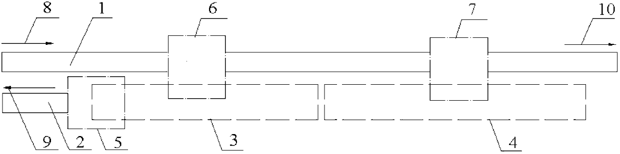
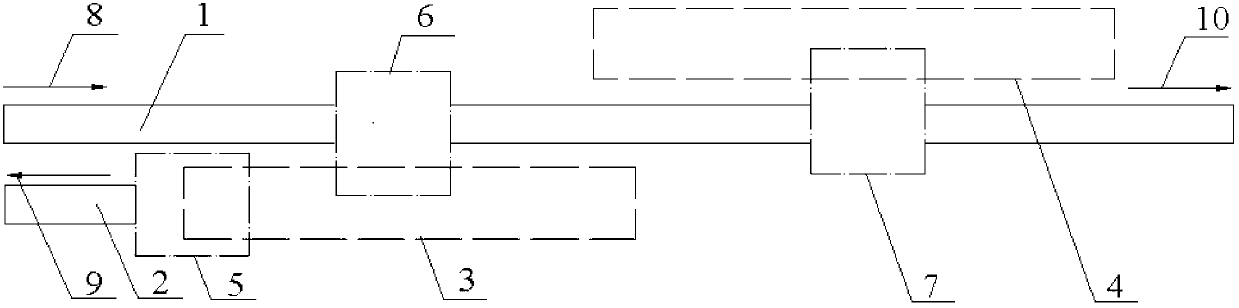
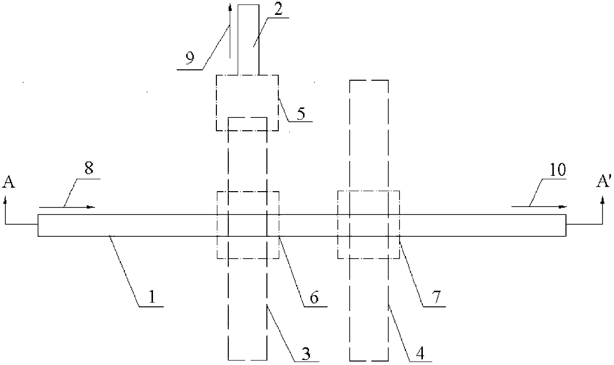
[0026] like figure 1 , figure 2 , image 3 As shown, it includes a bus waveguide 1, a drop waveguide 2, a drop waveguide microcavity 3, a reflective waveguide microcavity 4, a first coupling region 5, a second coupling region 6, and a third coupling region 7; the drop waveguide 2 and the drop waveguide The coupling area between the road waveguide microcavities 3 is the first coupling area 5, the coupling area between the bus waveguide 1 and the downstream waveguide microcavity 3 is the second coupling area 6, and the coupling area between the reflective waveguide microcavity 4 and the bus waveguide 1 is the second coupling area. Three coupling regions 7; the resonant frequency of the drop waveguide microcavity 3 and the reflective waveguide microcavity 4 are the same; The coupling rate of the drop waveguide microcavity 3 and the reflection waveguide...


PUM


Abstract

The invention discloses a lower path demultiplexing filter based on a wave guide type photon crystal microcavity. A coupled zone is formed between a lower path wave guide and a lower path wave guide microcavity, coupled zones are respectively formed between a bus wave guide and the lower path wave guide microcavity as well as between the bus wave guide and a reflecting wave guide microcavity; and the lower path wave guide microcavity and the reflecting wave guide microcavity are composed of one-dimensional photon crystal microcavities, and comprises a gradual changing lattice parameter zone in the middle of the microcavity and periodic lattice parameter zones on the two sides of the gradual change lattice parameter zone. The resonant frequency of the lower path wave guide microcavity is the same as that of the reflecting wave guide microcavity; and the coupling rate of the lower path wave guide microcavity and the reflecting wave guide microcavity to the lower path wave guide or bus wave guide is required to meet certain relation, and the length of the bus wave guide between the lower path wave guide microcavity and the reflecting wave guide microcavity is also required to meet certain conditions. The lower path demultiplexing filter is entirely based on the wave guide structure, and has the characteristics of simple structure, small size, high downloading efficiency, no echo at incidence port and the like, can be produced by adopting a plane wave guide process, and can be widely applied to on-chip superintegrated light wave division multiplexing interconnection systems.

Description

technical field [0001] The invention relates to a wavelength division multiplexing integrated optical device, in particular to an ultra-compact downlink demultiplexing filter based on a waveguide photonic crystal microcavity. Background technique [0002] With the increasing demand for communication in modern human society, optical fiber interconnection technology is also developing towards high capacity, large bandwidth and integration. The distance of optical communication and interconnection includes from as far as thousands of kilometers to the recently emerging very short-distance optical interconnection system integrated on the same chip. Optical wavelength division multiplexing (WDM) technology, which is widely used in optical fiber communication technology, can conveniently and effectively increase the system bandwidth capacity and improve the overall performance of the system. For on-chip optical interconnection technology, dense wavelength division multiplexing is...

Claims


Application Information

Patent Timeline
Patent Type & Authority Patents(China)
IPC IPC(8): G02B6/293H04J14/02
Inventor 喻平邱晨胡挺沈奥江晓清杨建义
Owner ZHEJIANG UNIV
Why Eureka
Try Eureka