
A non-reflection wave regulation and control device and a design method

A control device and design method technology, applied in computing, breakwaters, special data processing applications, etc., can solve the problems of no longer maintaining plane waves, reducing wave reflection, maintaining plane wave wave field characteristics, etc.

Active Publication Date: 2019-05-03
ZHEJIANG UNIV +1
View PDF8 Cites 3 Cited by
  • Summary
  • Abstract
  • Description
  • Claims
  • Application Information

AI Technical Summary

Problems solved by technology

[0002] When a plane wave encounters a solid structure, it will always reflect, causing the wave field around the solid structure to be disordered, and the characteristics of the plane wave will no longer be maintained.
In previous theoretical research and practice, there has been no effective way to reduce the reflection of waves while maintaining the wave field characteristics of plane waves

Method used


Image

  • A non-reflection wave regulation and control device and a design method
  • A non-reflection wave regulation and control device and a design method
  • A non-reflection wave regulation and control device and a design method

Examples


Embodiment 1

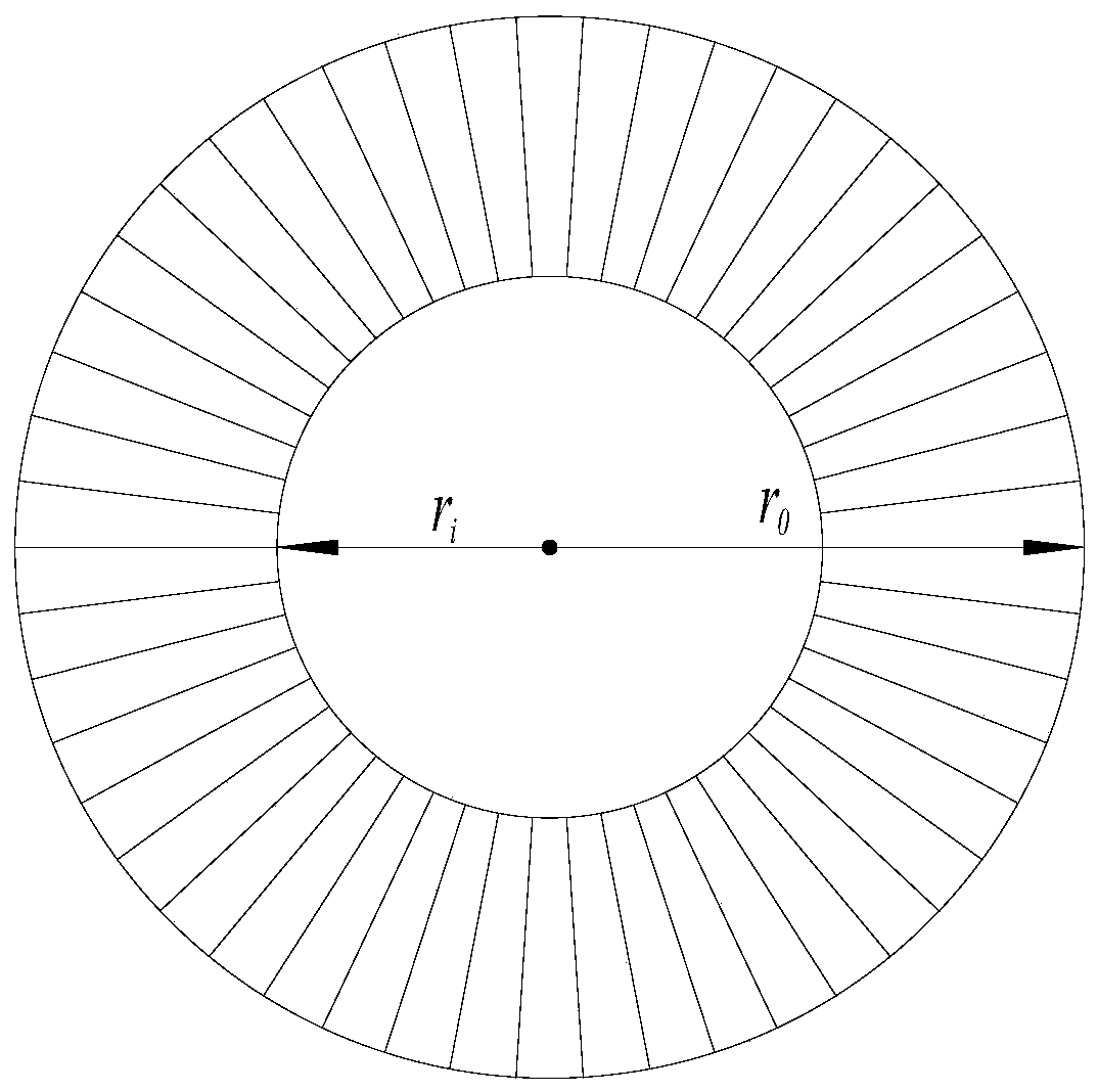
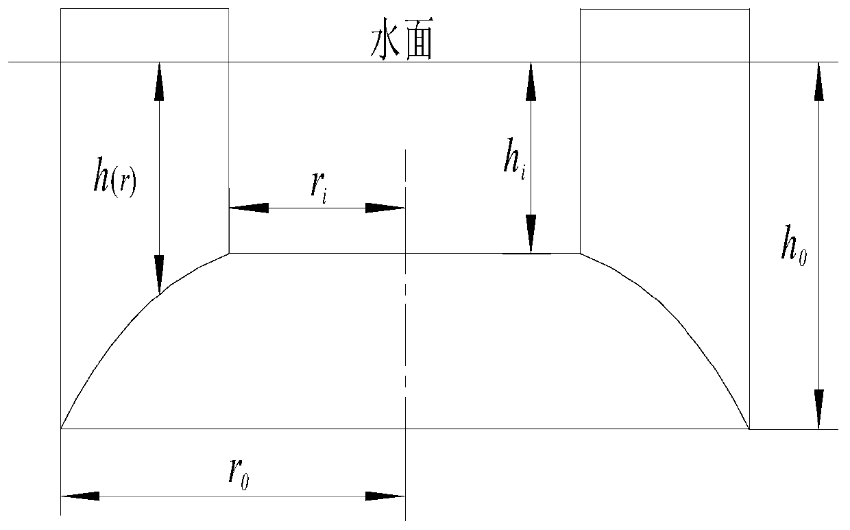
[0039] (1) Take a truncated cone-shaped body, the outer diameter of the upper bottom surface of the truncated cone-shaped body is r o =70mm, the inner diameter of the bottom surface is r i =35mm, the height of the body is H i =6mm, the side of the body is a highly gradual curved surface, which is formed by rotating a curve around the rotation axis of the body, such as figure 1 Shown

[0040] (2) Fifty baffles with a thickness of 1mm are uniformly arranged on the side of the body along the circumferential direction, and the baffles are placed in the radial direction of the body. The baffles start at the edge of the lower bottom surface of the body in the radial direction and end at the upper bottom surface of the body. Edge; a groove is formed between two adjacent baffles and the side surface of the body;

[0041] (3) When the body is immersed in water, the top of the baffle is higher than the water surface, and the depth of the bottom surface of the body is h 0 , H 0 =8mm; the depth...

Embodiment 2

[0054] (1) Take a truncated cone-shaped body, the outer diameter of the upper bottom surface of the truncated cone-shaped body is r o =428.88mm, the inner diameter of the bottom surface is r i =247.61mm, the height of the body is H i = 66.67mm, the side of the body is a highly gradual curved surface, the height gradual curved surface is formed by rotating a curve around the rotation axis of the body;

[0055] (2) On the side of the body, 50 baffles with a thickness of 0.5mm are evenly arranged along the circumferential direction, and the baffles are placed in the radial direction of the body. The baffles start from the edge of the lower bottom surface of the body in the radial direction and end on the upper part of the body. The edge of the bottom surface; a groove is formed between two adjacent baffles and the side surface of the body;

[0056] (3) When the body is immersed in water, the top of the baffle is higher than the water surface, and the depth of the bottom surface of the ...


PUM


Abstract

The invention discloses a non-reflection wave regulation and control device and a design method. The device has the same height of an area structure within the inner diameter ri, the height of the device at the outer diameter ro is 0, the height of the area structure between the inner diameter ri and the outer diameter ro is gradually changed, and a plurality of baffles are arranged in the heightgradually-changed area to form grooves. When the cone-frustum-shaped body is immersed in water and plane waves with specific wavelengths and frequencies are incident, the plane waves are hardly reflected on the periphery of the cone-frustum-shaped body, so that the wave energy loss on the periphery of the cone-frustum-shaped body is reduced, the waves entering the cone-frustum-shaped body are still the plane waves, and meanwhile, the wave amplitude is amplified.

Description

Technical field [0001] The invention belongs to the field of wave theory and engineering, and particularly relates to a non-reflective wave control device and a design method. Background technique [0002] When a plane wave encounters a solid structure, it will always be reflected, causing the wave field around the solid structure to be disordered and no longer maintain the characteristics of a plane wave. In the previous theoretical research and practice, there has been no effective way to reduce the reflection of waves while maintaining the wave field characteristics of plane waves. If a structure can be proposed that can significantly eliminate the wave reflection around the solid structure, or even without reflection, it can greatly reduce the wave energy loss around the solid structure, which is very valuable for improving the wave energy collection efficiency. In addition, this structure can be used for the measurement of wave field parameters, which can obtain the charact...

Claims


Application Information

Patent Timeline
Patent Type & Authority Applications(China)
IPC IPC(8): G06F17/50E02B3/06
CPCY02A10/11
Inventor 王振宇陈焕阳李春阳徐林
Owner ZHEJIANG UNIV
Learn More