

A waveguide stealth device applied to water waves and its design method
A water wave and waveguide technology, applied in the field of waveguide cloaking devices, can solve the problem of reducing wave amplitude and achieve the effect of wave amplitude reduction
- Summary
- Abstract
- Description
- Claims
- Application Information
AI Technical Summary
Problems solved by technology
Method used
Image


Examples
Embodiment 1
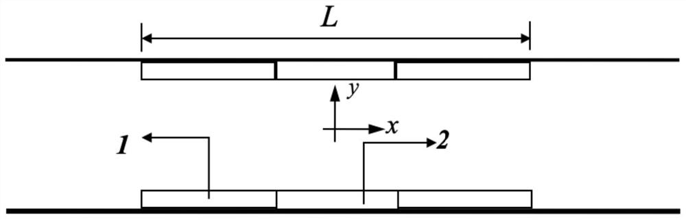
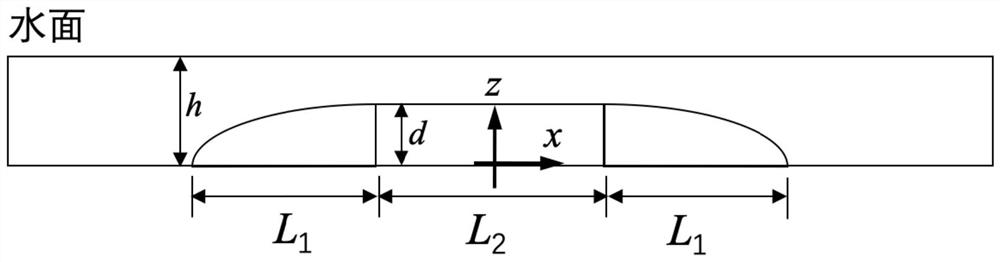
[0074] (1) Take an isosceles trapezoidal gentle slope structure composed of a slope section curved panel 1 and a horizontal section flat plate 2 as the body, and set a slope section with a length of 1.78m and a width of 0.15m at both ends of the similar trapezoidal gentle slope structure. The side is a height-gradient curved surface; the middle horizontal section area is set to a horizontal section with a length of 2.44m, a height of 0.133m, and a width of 0.15m. The total length of the body is 6m. The body is arranged side by side in the waveguide along the direction of water wave propagation; the top view is as follows: figure 1 As shown, the cross-sectional view is as figure 2 shown;
[0075] (2) When the body of the similar trapezoidal gentle slope structure is immersed in water, the water depth at the bottom of the body is h, h=0.15m; the height distribution of the body along the x-axis direction is recorded as d(x), then the water depth at the bottom of the body The wa...
Embodiment 2
[0087] (1) Take a plurality of cylinders with different diameters and an array spacing of 0.5m to form the main body of the cloaking device, arrange them in 13 rows, with 3 cylinders in each row, and the total length L of the main body is 6m. and the cylinders with the same spacing, the length is L 1 is 2m, such as image 3 and Figure 4 shown;
[0088] (2) The body is arranged in the water tank along the direction of water wave propagation. Let the direction of water wave propagation be the x-axis and the water depth direction as the y-axis. When the body is immersed in water, the water depth at the bottom of the body is 0.5m, and the height of the body is 0.7m. The body is equally spaced along the x-axis direction, and the refractive index distribution of the body along the x-axis direction is recorded as n(x), and n(x) satisfies the formula in the x direction:
[0089] 1) When -11 , then the refractive index of this region can be expressed as: n2(x)=N 1 =1.5
[0090] 2...
Embodiment 3
[0098](1) Take five right-angled trapezoidal structures composed of slope section curved panels and horizontal section flat plates and arrange them side by side continuously as the main body; set a slope section with a length of 1.78m and a width of 0.15m at one end of the right-angled trapezoidal gentle slope structure, and the slope section The side is a height-gradient curved surface; the middle horizontal section area is set to a horizontal section with a length of 4.22m, a height of 0.133m, and a width of 0.15m. The total length of the main body is 6m. The main body is arranged side by side in the waveguide along the direction of water wave propagation; Figure 5 As shown, the cross-sectional view is as Figure 6 shown;
[0099] (2) When the body of the quasi-right-angled trapezoidal structure is immersed in water, the water depth at the bottom of the body is h, where h=0.15m; the height distribution of the body along the x-axis direction is denoted as d(x), and the The ...
PUM
 Abstract
Description
Claims
Application Information