Light pulse shaper based on double-array fiber grating and working method thereof

A fiber grating, optical pulse technology, applied in the coupling of optical waveguides, optics, instruments, etc., can solve the problems of dynamic changes, the shaper is not dynamic, etc., to achieve the effect of bandwidth upgrade, simple structure, and easy bandwidth

Inactive Publication Date: 2014-06-04
TIANJIN UNIVERSITY OF TECHNOLOGY
View PDF5 Cites 0 Cited by
  • Summary
  • Abstract
  • Description
  • Claims
  • Application Information

AI Technical Summary

Problems solved by technology

However, the reflectivity profile of the complex fiber grating requires a higher precision manufacturing process, and the manufactured shaper is not dynamic, and cannot change dynamically with the input waveform and the target waveform. Therefore, we propose a dual-array fiber Bragg The phase control of the grating and the structure of the interference effect realize the dynamic optical pulse shaping

Method used


Image

  • Light pulse shaper based on double-array fiber grating and working method thereof
  • Light pulse shaper based on double-array fiber grating and working method thereof
  • Light pulse shaper based on double-array fiber grating and working method thereof

Examples


Embodiment 1

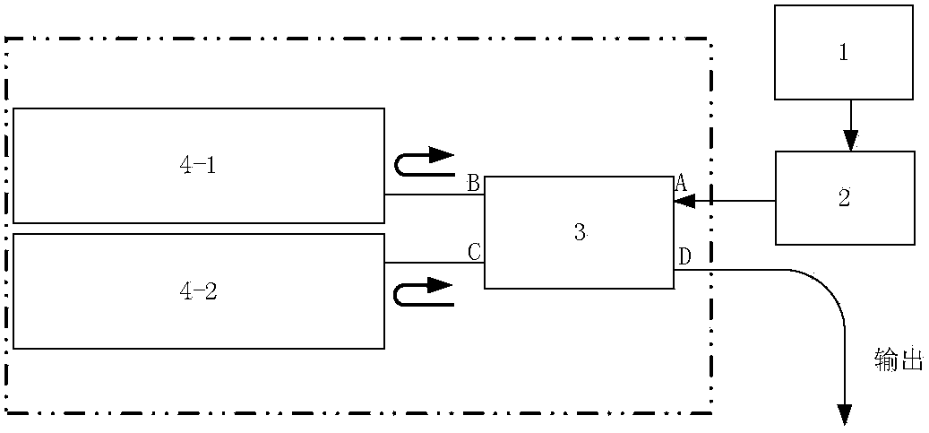
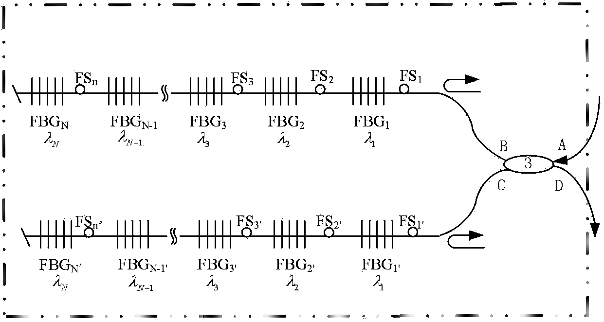
[0040] Embodiment 1: An optical pulse shaper based on a dual-array fiber grating, characterized in that it is composed of an optical frequency comb source 1, an optical isolator 2 and an amplitude controller, and the output end of the optical frequency comb source 1 is connected to the optical isolator The input end of the optical isolator 2 is connected to the input end of the amplitude controller, and the output end of the amplitude controller outputs periodic Gaussian optical pulses; the amplitude controller consists of two fiber Bragg grating arrays 4-1 and 4-2 and coupler 3, port A of coupler 3 is connected to the output end of optical isolator 2, port B and port C of coupler 3 are respectively connected to two fiber Bragg grating arrays 4-1 and 4-2, coupled Port D of the device 3 is the output end of the amplitude controller to output periodic Gaussian optical pulses; the said fiber Bragg grating array is composed of 21 fiber Bragg gratings and 21 fiber stretchers arranged...

Embodiment 2

[0063] Embodiment 2: An optical pulse shaper based on a dual-array fiber grating, characterized in that it consists of an optical frequency comb source 1, an optical isolator 2 and an amplitude controller, and the output end of the optical frequency comb source 1 is connected to the optical isolator The input terminal of the optical isolator 2 is connected to the input terminal of the amplitude controller, and the output terminal of the amplitude controller outputs periodic triangular light pulses; the amplitude controller consists of two fiber Bragg grating arrays 4-1 and 4-2 and coupler 3, port A of coupler 3 is connected to the output end of optical isolator 2, port B and port C of coupler 3 are respectively connected to two fiber Bragg grating arrays 4-1 and 4-2, coupled Port D of the device 3 is the output terminal of the amplitude controller to output periodic triangular light pulses; the said fiber Bragg grating array is composed of 21 fiber Bragg gratings and 21 fiber st...

Embodiment 3

[0086] Embodiment 3: An optical pulse shaper based on a dual-array fiber grating, characterized in that it is composed of an optical frequency comb source 1, an optical isolator 2 and an amplitude controller, and the output end of the optical frequency comb source 1 is connected to the optical isolator The input end of the optical isolator 2 is connected to the input end of the amplitude controller, and the output end of the amplitude controller outputs periodic bilateral exponential optical pulses; the amplitude controller consists of two fiber Bragg grating arrays 4-1 It is composed of 4-2 and coupler 3. Port A of coupler 3 is connected to the output end of optical isolator 2, and port B and port C of coupler 3 are respectively connected to two fiber Bragg grating arrays 4-1 and 4-2, The port D of the coupler 3, which is the output end of the amplitude controller, outputs periodic bilateral exponential light pulses; the fiber Bragg grating array is composed of 41 fiber Bragg g...


PUM


Abstract

The invention relates to a light pulse shaper based on a double-array fiber grating, comprises an optical frequency comb source, an optoisolator and an amplitude controller, wherein the output end of the optical frequency comb source is connected with the input end of the optoisolator, the output end of the optoisolator is connected with the input end of the amplitude controller, and the output end of the amplitude controller outputs even function waveform light pulses. A working method of the light pulse shaper based on the double-array fiber grating comprises the following steps of: (1) inputting; (2) controlling amplitudes: splitting light, adjusting phases, and interfering; and (3) outputting. In the invention, the size of light spectrum amplitudes can be continuously accurately changed by only using a fiber stretcher, thereby realizing the dynamic adjustment of the light spectrum amplitudes; simple structure, little loss and easy coupling with other optical devices are achieved; random waveform light pulses of even function waveforms can be output; and shaping bandwidth can be increased by increasing the wavelength interval of adjacent gratings or increasing the number of gratings, thereby enabling the bandwidth of the device to be easy to upgrade.

Description

(1) Technical field: [0001] The invention relates to an ultrashort optical pulse shaper and a working method thereof, in particular to a line-by-line shaping of an input optical pulse in the frequency domain by using the phase control and interference effect of a dual-array fiber Bragg grating to control the amplitude of each spectral line , A light pulse shaper capable of realizing arbitrary even function waveform and its working method. (2) Background technology: [0002] In the past two decades, due to the development of ultra-short optical pulse technology and the widespread use of femtosecond laser systems, and many applications also require ultra-fast light pulses, light pulses of arbitrary shapes, pulse shaping systems have achieved rapid The development of ultrafast laser spectroscopy, nonlinear fiber optics, high energy physics and other fields have had a significant impact. Arbitrary Waveform Optical Pulse Generation (O-AWG) technology has many applications in the fiel...

Claims


Application Information

Patent Timeline
Patent Type & Authority Patents(China)
IPC IPC(8): G02B27/09G02B6/34
Inventor 张爱玲李长秀
Owner TIANJIN UNIVERSITY OF TECHNOLOGY
Why Eureka
Try Eureka