
A laser display terminal

A laser display and terminal technology, applied in the field of laser technology, can solve problems such as frequency-doubled laser output power instability, frequency-doubled light output power fluctuations, fundamental frequency light gain intensity changes, etc., to alleviate the problem of green light, expand uses and function, the effect of increasing the wavelength interval

Active Publication Date: 2018-06-19
HISENSE VISUAL TECH CO LTD
View PDF4 Cites 0 Cited by
  • Summary
  • Abstract
  • Description
  • Claims
  • Application Information

AI Technical Summary

Problems solved by technology

[0006] However, in the prior art, when the laser is outputting the frequency-doubled laser, the output power of the frequency-doubled laser is unstable, and even the power fluctuation is relatively large, mainly because when the fundamental frequency light of different frequencies is frequency-doubled, due to The mutual saturation effect between the modes causes the competition of the fundamental frequency light between different frequencies, which causes the gain intensity of the fundamental frequency light to change when gaining, and the output power of the double frequency light fluctuates, which is the so-called green light problem
[0007] In the prior art, it can be solved by changing the length of the mirror cavity, such as increasing the length of the mirror cavity to increase the longitudinal modulus, or shortening the length of the mirror cavity to reduce the longitudinal modulus. However, the above-mentioned long mirror cavity method and short mirror The cavity method too much limits the mirror cavity length of the laser, which brings many restrictions to the design of the laser; in the prior art, a self-stabilizing system can also be used to control the output, but this method increases the production cost of the laser

Method used


Image

  • A laser display terminal
  • A laser display terminal
  • A laser display terminal

Examples


Embodiment Construction

[0071] The technical solution of the present invention will be further described in detail below through the drawings and embodiments.

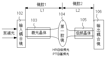
[0072] figure 1 It is a schematic structural diagram of a laser processing device in an embodiment of the present invention. Such as figure 1 As shown, the laser processing apparatus of the embodiment of the present invention may include:

[0073] A chamber, the input end of the chamber receives the pump light, the chamber is provided with a laser crystal 103 and a wavelength conversion unit, the laser crystal 103 excites the pump light to generate fundamental frequency light, and the wavelength conversion unit performs wavelength conversion on the fundamental frequency light After the laser is output, the wavelength conversion unit may be a frequency doubling crystal 105.

[0074] A first cavity mirror 104 is provided between the laser crystal 103 and the wavelength conversion unit in the cavity for high reflection of frequency-doubled light or mu...


PUM


Abstract

The embodiment of the invention discloses a laser processing device, a laser processing method and a laser display light source and relates to the field of laser techniques. The laser processing device, the laser processing method and the laser display light source aim to solve the problem of unstable power of frequency multiplication light output by a laser unit in the prior art. A laser display terminal comprises a pump light emitter, the laser processing device and a display screen, the pump light emitter outputs pump light, lasers are output and used for displaying video images on the display screen after the pump light passes through the laser processing device, the laser processing device comprises a first cavity mirror and at least one second cavity mirror, the first cavity mirror is used for transmitting a part of fundamental frequency light, each second cavity mirror is used for transmitting a part of the fundamental frequency light and arranged between the first cavity mirror and a laser crystal, longitudinal mode selection of the fundamental frequency light is further achieved, the amount of the fundamental frequency light in a resonant cavity is greatly reduced, fundamental frequency light of a single longitudinal mode can be obtained, the green problem is relieved, and power stability of frequency multiplication light output is improved.

Description

[0001] This application is a divisional application of the Chinese invention patent application CN201080066241.6 (PCT / CN2010 / 071842) filed on April 16, 2010 with the title of "a laser generating device and method". Technical field [0002] The present invention relates to laser technology, in particular to a laser display terminal. Background technique [0003] The laser has the characteristics of good monochromaticity, strong directionality and high brightness. The core of laser technology is lasers. There are many types of lasers, which can be classified according to different methods such as working substance and working wavelength. [0004] Nowadays, laser technology has begun to find applications in TV, micro-projection, commercial and entertainment systems. The laser frequency doubling technology has greatly expanded the existing laser frequency, not only achieving the laser output in the visible light band, but also using the triple frequency and quadruple frequency technolo...

Claims


Application Information

Patent Timeline
Patent Type & Authority Patents(China)
IPC IPC(8): H01S3/109
Inventor 闫国枫陈昱
Owner HISENSE VISUAL TECH CO LTD
Learn More