Thermal overload relay with current transformers

A thermal overload relay, current transformer technology, applied in circuits, electrical components, parts of protection switches, etc., to prevent electric shock hazards and avoid the effect of heat

Active Publication Date: 2012-10-03
SHANGHAI NOARK ELECTRIC
View PDF5 Cites 1 Cited by
  • Summary
  • Abstract
  • Description
  • Claims
  • Application Information

AI Technical Summary

Problems solved by technology

[0004] The purpose of the present invention is to provide a thermal overload relay with a current transformer that overcomes the above defects. By integrating the thermal release and the current transformer into a thermal overload relay with a current tr

Method used


Image

  • Thermal overload relay with current transformers
  • Thermal overload relay with current transformers
  • Thermal overload relay with current transformers

Examples


Embodiment Construction

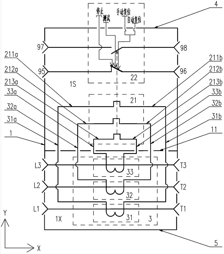
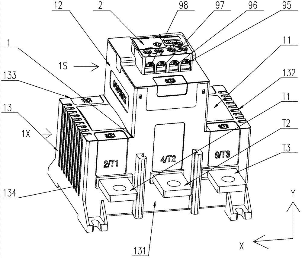
[0029] The following is attached Figure 1-11 Several specific implementations of the thermal overload relay with current transformer of the present invention are described in detail, wherein Figure 1-8 Can be generally used in the first embodiment or the second embodiment of the thermal overload relay with current transformer of the present invention, and Figure 9-11 It is only applicable to the first embodiment of the thermal overload relay with current transformer of the present invention. The current transformer of the first embodiment is arranged in a zigzag shape, and the current transformer of the second embodiment is arranged in a zigzag shape (not shown in the drawings). out). The thermal overload relay with current transformer of the present invention is not limited to the description of the following embodiments.

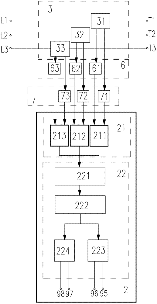
[0030] figure 1 It is a functional block diagram of the thermal overload relay with current transformer of the present invention, in which the conne...


PUM


Abstract

Disclosed is a thermal overload relay with current transformers. An overall double-layer casing of the thermal overload relay consists of a transversely extending partition support, a longitudinally extending upper bucket-shaped casing wall and a longitudinally extending lower bucket-shaped casing wall. A thermal release is installed inside an upper cavity of the overall double-layer casing. Three current transformers are installed inside a lower cavity of the overall double-layer casing. Two leads of a secondary coil of each current transformer pass from the lower cavity into the upper cavity by passing through holes at the joint of the partition support with the upper and lower cavities. The thermal overload relay further comprises an L-side junction device and a T-side junction device both disposed inside the upper cavity. An L-side lead of each electric heater is connected with one lead of the corresponding current transformer through an L-side junction component, and a T-side lead of each electric heater is connected with the other lead of the corresponding current transformer through a T-side junction component. A relay panel is fixedly connected with the upper bucket-shaped casing wall. The devices and leads thereof are all hermetically disposed inside the upper cavity, while terminals extend out of the upper cavity through a window of the relay panel. A bottom plate is used for closing all current transformers in the lower cavity of the double-layer casing.

Description

technical field [0001] The invention relates to a thermal overload relay, in particular to a thermal double gold overload relay with a current transformer. Background technique [0002] Thermal overload relay, referred to as thermal relay or thermal tripper, is a low-voltage electrical appliance widely used in overload protection of electric loads or AC motors, and can also be combined with a contactor to form an electromagnetic starter. Thermal bimetallic overload relay is the most commonly used thermal relay. It uses a bimetal sheet with delay characteristics as a thermal element. It not only has the function of overload protection, but also has the function of phase failure protection. The gold piece is connected in series to the line on the input side of the load such as the motor. When the motor is overloaded or a phase failure occurs in the three-phase line, the current of at least one phase line will increase, so that the double gold piece connected to the phase line ...

Claims


Application Information

Patent Timeline
IPC IPC(8): H01H71/14H01H71/02
Inventor 何化敏李伟
Owner SHANGHAI NOARK ELECTRIC
Why Eureka
Try Eureka