
Scanning device

A scanning device and technology to be scanned are applied in the direction of image communication and electrical components, which can solve the problems of reducing the volume of the scanning device and increasing the scanning process time, and achieve the effects of avoiding light interference, compact structure, and improving brightness

Inactive Publication Date: 2012-10-03
QISDA SUZHOU
View PDF4 Cites 3 Cited by
  • Summary
  • Abstract
  • Description
  • Claims
  • Application Information

AI Technical Summary

Problems solved by technology

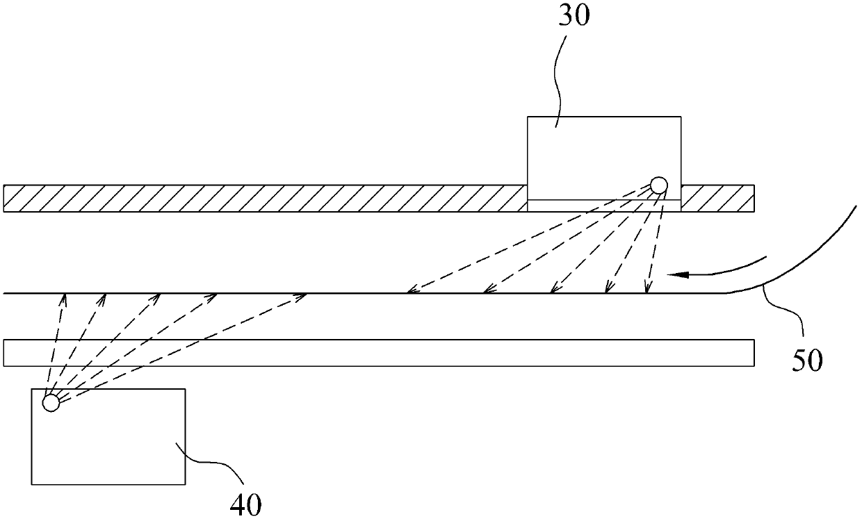
like figure 1 As shown, the existing double-sided scanning device includes two scanning modules on the upper and lower sides to scan both sides of the manuscript 50 to be scanned, and the first scanning module 30 located above is used to scan the first side of the manuscript 50 to be scanned; The second scanning module 40 below is used to scan the second side of the manuscript 50 to be scanned. In order to avoid that the first scanning module 30 and the second scanning module 40 scan simultaneously, the The light and the light emitted by the light source of the second scanning module 40 pass through the manuscript 50 and affect the scanning of the two scanning modules. Therefore, the first scanning module 30 and the second scanning module 40 are far away from each other. This method will not cause light interference between scanning modules, but it is not conducive to reducing the size of the entire scanning device and will increase the time of the entire scanning process

Method used


Image

  • Scanning device
  • Scanning device
  • Scanning device

Examples


Embodiment Construction

[0021] In order to have a further understanding of the purpose, structure, features, and functions of the present invention, the following detailed descriptions are provided in conjunction with the embodiments.

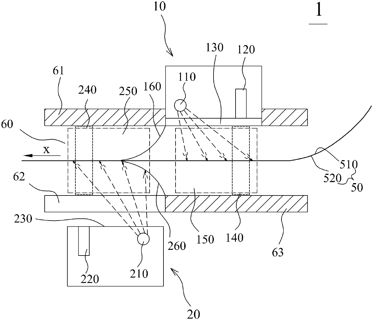
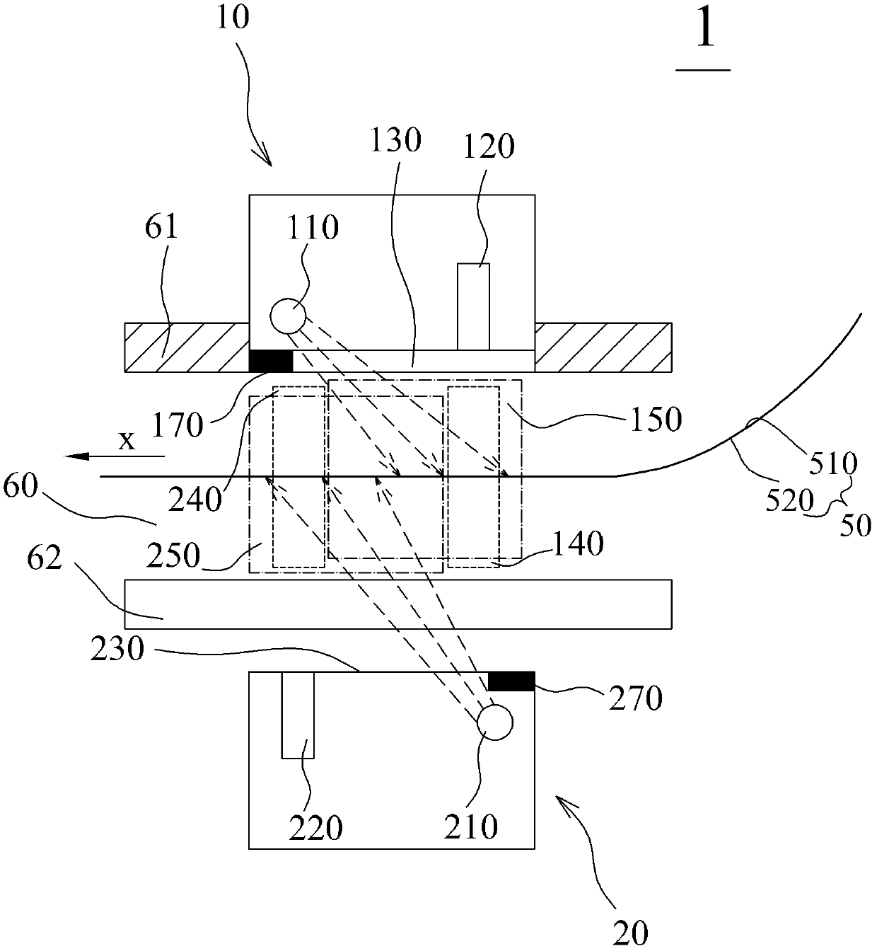
[0022] Please refer to Figure 2 to Figure 6 , the scanning device 1 of the present invention includes a first scanning module 10 and a second scanning module 20 for double-sided scanning of a manuscript 50 to be scanned. The scanning device 1 further includes an automatic document feeder (Automatic Document Feeder, ADF), and the document 50 to be scanned is automatically transported along the transport direction x in the transport channel 60 through the automatic document feeder. The transmission channel 60 is formed by the upper casing 61 of the scanning device 1 and the glass platform 62 arranged opposite to each other. The first scanning module 10 is fixed on the upper casing 61 , and the second scanning module is disposed under the glass platform 62 .

[0023] ...


PUM


Abstract

The invention provides a scanning device. The scanning device comprises a first scanning module and a second scanning module and is used for conducting double-side scanning on a manuscript to be scanned. The first scanning module comprises a first light source, a first imaging section and a first scanning window, an area which corresponds to the first imaging section and is located in a transmission channel is defined as a first scanning area, and an area which is located in the transmission channel and irradiated by a ray of light sent out by the first light source through the first scanning window is defined as a first irradiation area. The second scanning module comprises a second light source, a second imaging section and a second scanning window, an area which corresponds to the second imaging section and is located in the transmission channel is defined as a second scanning area, and an area which is located in the transmission channel and irradiated by a ray of light sent out by the second light source through the second scanning window is defined as a second irradiation area. The first scanning area is not overlapped with the second irradiation area, and the second scanning area is not overlapped with the first irradiation area. The scanning device is compact in structure, and simultaneously, light interference between the first scanning module and the second scanning module can be avoided.

Description

technical field [0001] The invention relates to a scanning device, in particular to a double-sided scanning device. Background technique [0002] The scanning device has become one of the essential office equipment, and it is developing towards the direction of high-speed scanning function, miniaturization and portability. Such as figure 1 As shown, the existing double-sided scanning device includes two scanning modules on the upper and lower sides to scan both sides of the manuscript 50 to be scanned, and the first scanning module 30 located above is used to scan the first side of the manuscript 50 to be scanned; The second scanning module 40 below is used to scan the second side of the manuscript 50 to be scanned. In order to avoid that the first scanning module 30 and the second scanning module 40 scan simultaneously, the The light and the light emitted by the light source of the second scanning module 40 pass through the manuscript 50 and affect the scanning of the two...

Claims


Application Information

Patent Timeline
IPC IPC(8): H04N1/04
Inventor 张智海
Owner QISDA SUZHOU
Learn More