Servo ventilation using pressure drop from baseline

A baseline, pressure technique, applied in the direction of pharmaceutical equipment, other medical equipment, breathing masks, etc.

Active Publication Date: 2012-10-03
KONINK PHILIPS ELECTRONICS NV
View PDF20 Cites 9 Cited by
  • Summary
  • Abstract
  • Description
  • Claims
  • Application Information

AI Technical Summary

Problems solved by technology

However, this approach requires additional equipment used with typical ventilator systems

Method used


Image

  • Servo ventilation using pressure drop from baseline
  • Servo ventilation using pressure drop from baseline
  • Servo ventilation using pressure drop from baseline

Examples


Embodiment Construction

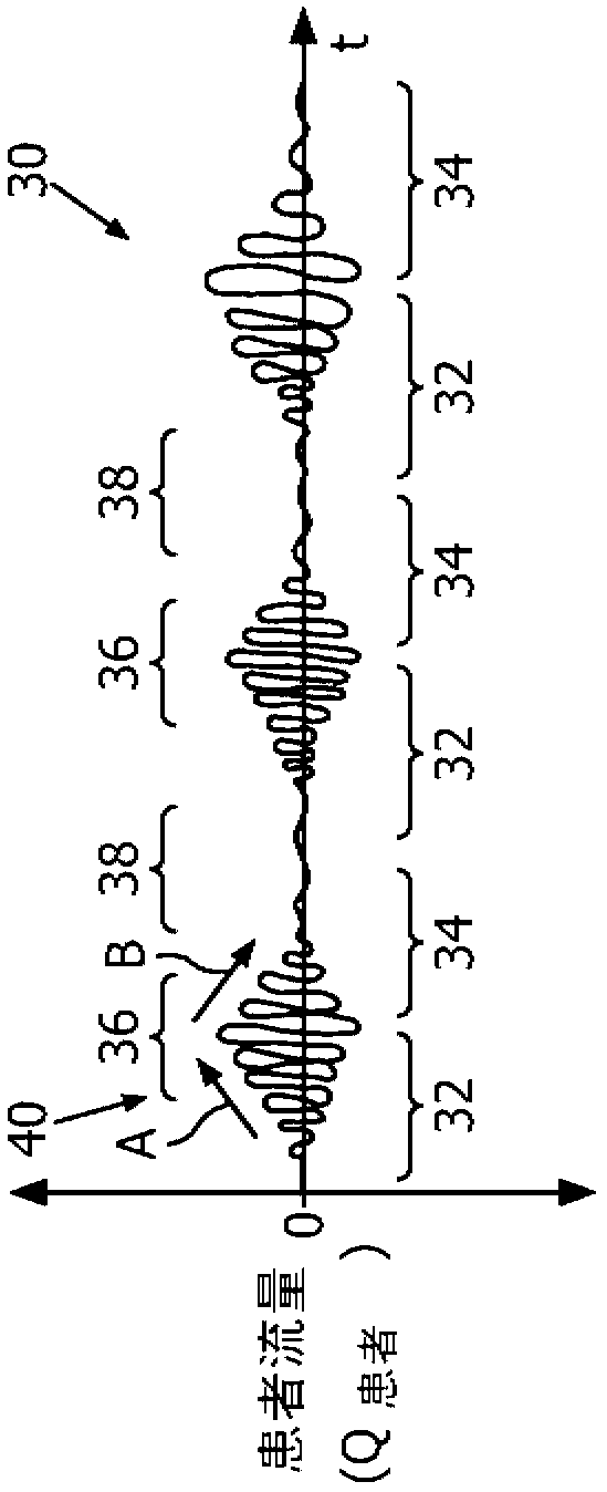
[0019] Figure 2A illustrates a waveform, i.e., a graph of the measured flow rate at the patient's airway, and Figure 2B Illustrated, according to an embodiment, by the pressure support system 10 (see image 3 ) waveform of the pressure support delivered to the patient. System 10 may use these patient flow values ​​to obtain other measurements of patient flow, such as, for example, peak flow, minute ventilation, tidal volume, mean inspiratory flow, or other measurements. Initially, as in Figure 2B Indicated by arrow C in , the patient experienced a CSR event. During the hyperpneic phase of the CSR mode, as indicated by arrow D, negative pressure support is activated and delivered to the patient. Positive and negative pressure support may be applied until the CSR event has been reduced or eliminated. Positive pressure support as used herein is for situations where the inspiratory pressure level, such as IPAP, is higher than the expiratory pressure level, such as EPAP. I...


PUM


Abstract

A system and method for delivering a flow of breathing gas to an airway of a patient that includes a gas flow generator and a patient circuit that communicates the flow of gas to an airway of a patient. A sensor measures a characteristic associated with the flow of gas, such as flow rate. A controller determines a first characteristic based on the measured characteristic and a target of the flow of gas to be delivered to the patient. The controller controls the delivery of gas to the patient by 1) providing a baseline positive pressure support amount to the patient and 2) providing a modified pressure support amount by reducing the baseline amount by a given amount if the first characteristic is above the target. The baseline pressure includes a pressure provided during inspiration that is higher than a pressure provided during expiration.

Description

[0001] This patent application claims priority under 35 U.S.C. §119(e) to U.S. Provisional Application No. 61 / 294875, filed January 14, 2010, the contents of which are hereby incorporated by reference. technical field [0002] The present invention relates generally to methods and devices for providing pressure therapy particularly suited for the management of tidal breathing and other breathing disorders commonly associated with congestive heart failure. Background technique [0003] Patients with congestive heart failure (CHF) often suffer from a breathing disorder such as obstructive sleep apnea (OSA) or central apnea. Another such breathing disturbance often experienced by CHF patients during sleep is known as tidal breathing. figure 1 A typical tidal breathing (CSR) pattern 30 is illustrated, characterized by a rhythmic crescendo 32 and a 34 There is a regular recurring cycle of high respiratory drive (hyperpnea) 36 and low respiratory drive (hypopnea or apnea) 38 . A...

Claims


Application Information

Patent Timeline
Patent Type & Authority Applications(China)
IPC IPC(8): A61M16/00
CPCA61M2016/0009A61M2016/0039A61M16/0066A61M16/00A61M16/06A61M16/20A61M16/0875A61M2016/204A61M2209/01A61M2205/7518A61M2016/0069A61M2205/50A61M2205/502A61M16/0009A61M16/0069A61M16/204A61M16/024
Inventor B·I·谢利M·T·凯恩G·D·马修斯
Owner KONINK PHILIPS ELECTRONICS NV
Why Eureka
Try Eureka