
A wing of an aircraft

A wing and aircraft technology, applied in the field of aircraft wings, can solve the problems of crashes, no longer ensuring fluid correction around the wings, unstable flight conditions, etc., to achieve the effect of increasing the safety level

Active Publication Date: 2012-10-03
AIRBUS OPERATIONS GMBH
View PDF7 Cites 3 Cited by
  • Summary
  • Abstract
  • Description
  • Claims
  • Application Information

AI Technical Summary

Problems solved by technology

All the situations cited illustrate important safety risks, where correction of fluid around the wings can no longer be ensured, and unstable flight conditions risk crashing in extreme cases

Method used


Image

  • A wing of an aircraft
  • A wing of an aircraft
  • A wing of an aircraft

Examples


Embodiment Construction

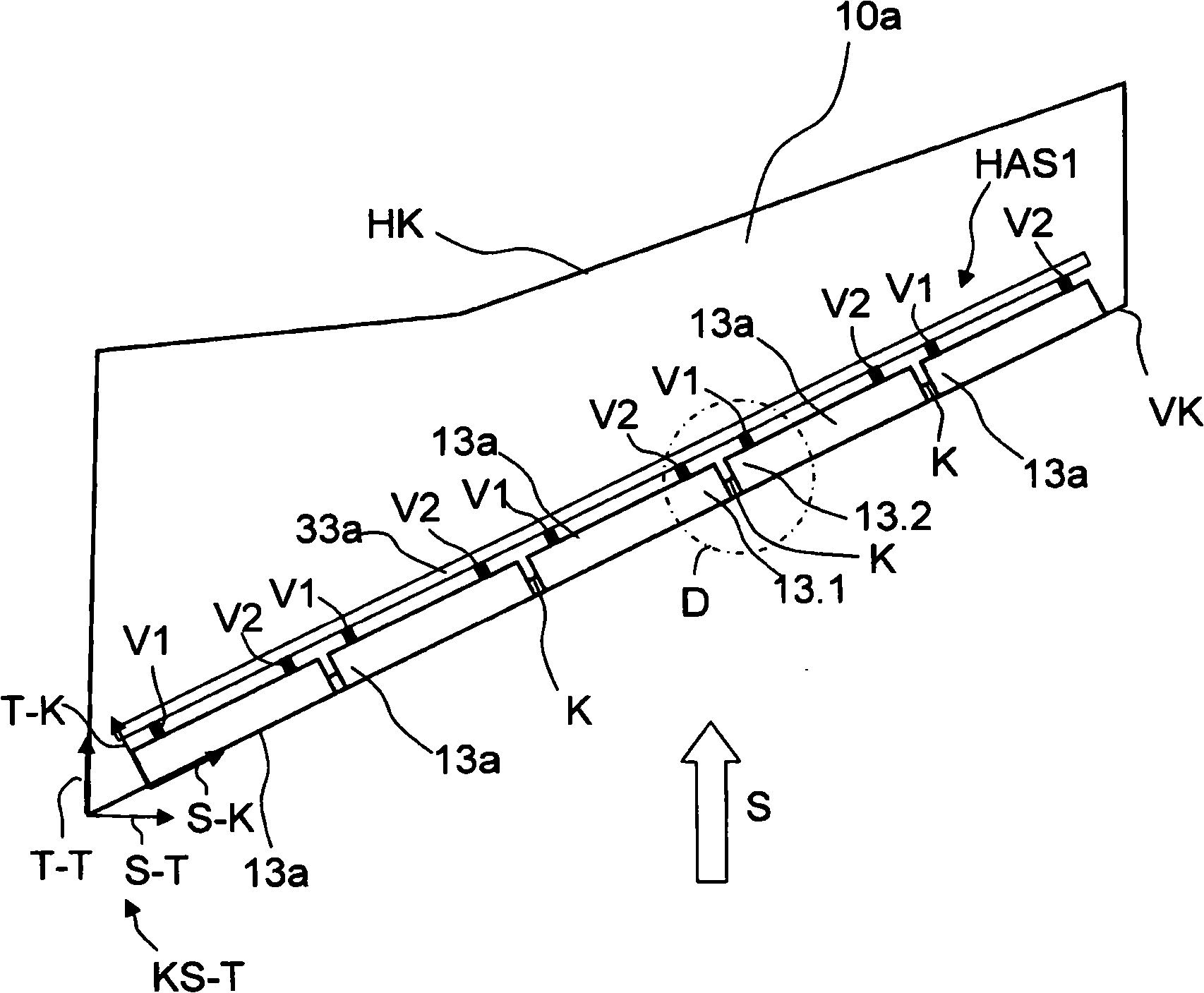
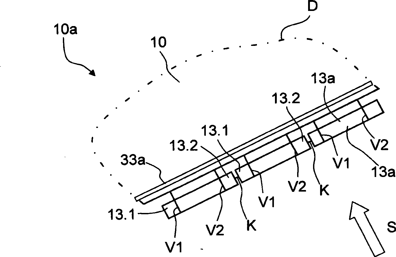
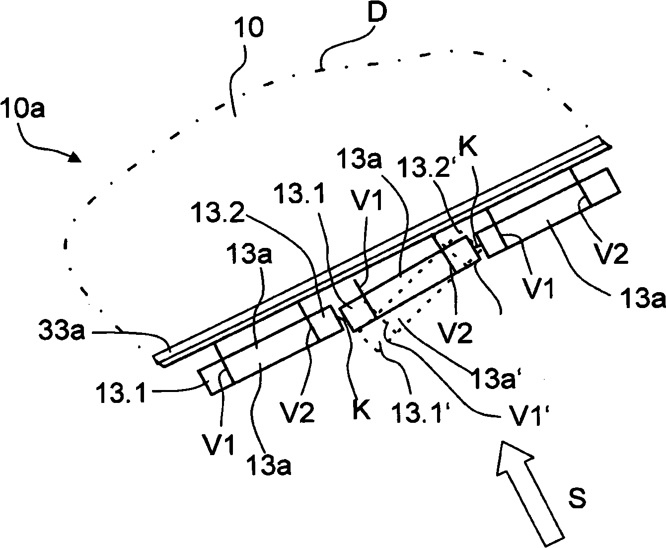
[0023] The present invention relates to a wing of a high-lift system, especially including a leading edge lift system (leading edge lift system) HAS1. According to the invention the aircraft or its wings may comprise a leading edge high lift system HAS1, and additionally a trailing edge high lift system (not shown). Generally, the leading-edge high-lift system HAS1 provided is used for positioning at least one leading-edge high-lift body or a leading-edge positioning body, which can be a slat or a leading-edge flap. The provided trailing edge high-lift system is used for positioning at least one trailing edge high-lift body or a trailing edge positioning body, which can be a landing flap, or a leading edge flap, or a flap that can rotate on the wing.

[0024] figure 1 The illustrated embodiment of the wing 10a is assigned in order to determine the orientation under a wing coordinate system KS-T, which has a coordinate axis S-T along the span direction and a coordinate axis T-...


PUM


Abstract

A wing (10a) of an aircraft provided with a main wing (10) and an arrangement of leading edge lifting bodies (13a), which as seen with reference to the incident flow direction (F) are arranged on the leading edge, which are adjustably arranged on the main wing (10) one behind another as seen in the spanwise direction (S-T) of the main wing (10) by means of respectively two positioning devices spaced apart from one another in the spanwise direction (S-T) of the main wing, wherein the wing (10a) has a connecting device (K), which is coupled to each of two adjacent leading edge lifting bodies (13a), wherein the connecting device (K) is executed such that in the event of a fracture of a positioning device of a positioning body external forces acting on the latter are transferred via the respective connecting device (K) to the leading edge lifting bodies (13a) coupled up via the latter.

Description

technical field [0001] The invention relates to an aircraft wing, which has a main wing and a plurality of wing leading edge booster structures, and the leading edge booster bodies respectively pass through the wings of the main wing when viewed from the span direction of the main wing. Two positioning devices spaced apart from each other in the span direction are adjustably arranged on the main wing in a manner that one follows the other. Background technique [0002] Prior art wings of this type are known art, having a leading edge booster body, which is adjustable relative to the main wing according to the phase of flight, ie phases such as take-off, climb, cruise, descent and landing. In each flight regime, different airflows dominate over the wings of the aircraft. In order to generate and maintain the most aerodynamic shape possible, and / or the highest possible lift, the profile of an aircraft wing must comply with the stated flight conditions. [0003] So-called dro...

Claims


Application Information

Patent Timeline
IPC IPC(8): B64C9/22
CPCB64C9/22
Inventor 泽维尔・休伯恩哈德・施利普夫
Owner AIRBUS OPERATIONS GMBH
Learn More