Bulk feeder parts holding case

A storage container and feeder technology, applied to electrical components, electrical components, conveyor objects, etc., can solve the problems of parts spilling outside, taking a long time, and poor storage space

Active Publication Date: 2012-10-03
TAIYO YUDEN KK
View PDF6 Cites 8 Cited by
  • Summary
  • Abstract
  • Description
  • Claims
  • Application Information

AI Technical Summary

Problems solved by technology

[0014] However, in the methods M1 and M2 of the above-mentioned "parts replenishment work", since the parts stored in packages such as bags or containers must be directly replenished into the storage room of the bulk feeder, even skilled workers may It also takes a considerable amount of time, and there is also the disadvantage that parts are spilled outside when an unskilled person operates.
In addition, in the method M3 of the above-mentioned "parts change work", since it is necessary to prepare and store a plurality of bulk feeders for part change in advance, there is a disadvantage that a corresponding storage space is required, and there is also a problem that maintenance is required. Defects of the bulk feeder for parts change

Method used


Image

  • Bulk feeder parts holding case
  • Bulk feeder parts holding case
  • Bulk feeder parts holding case

Examples


no. 1 approach

[0061] First, quote figure 1 , the "components that can be accommodated in the component storage container", that is, the components that can be used as supply objects will be described.

[0062] figure 1 The part PA1 shown in (A) is a rectangular parallelepiped having the dimensional relationship of length L1>width W1=height H1, figure 1 The part PA2 shown in (B) is a rectangular parallelepiped having the dimensional relationship of length L2>width W2>height H2, figure 1 Part PA3 shown in (C) has a cylindrical shape having a dimensional relationship of length L3>diameter R3.

[0063] Representative examples of these components PA1 to PA3 are electronic components such as small chip capacitors (chip condensers) and chip registers whose lengths L1 to L3 are 1.6 mm, 1.0 mm, 0.6 mm, or 0.4 mm. These electronic parts generally have external electrodes containing ferromagnetic materials, and depending on the type, also have internal conductors containing ferromagnetic materials,...

no. 2 approach

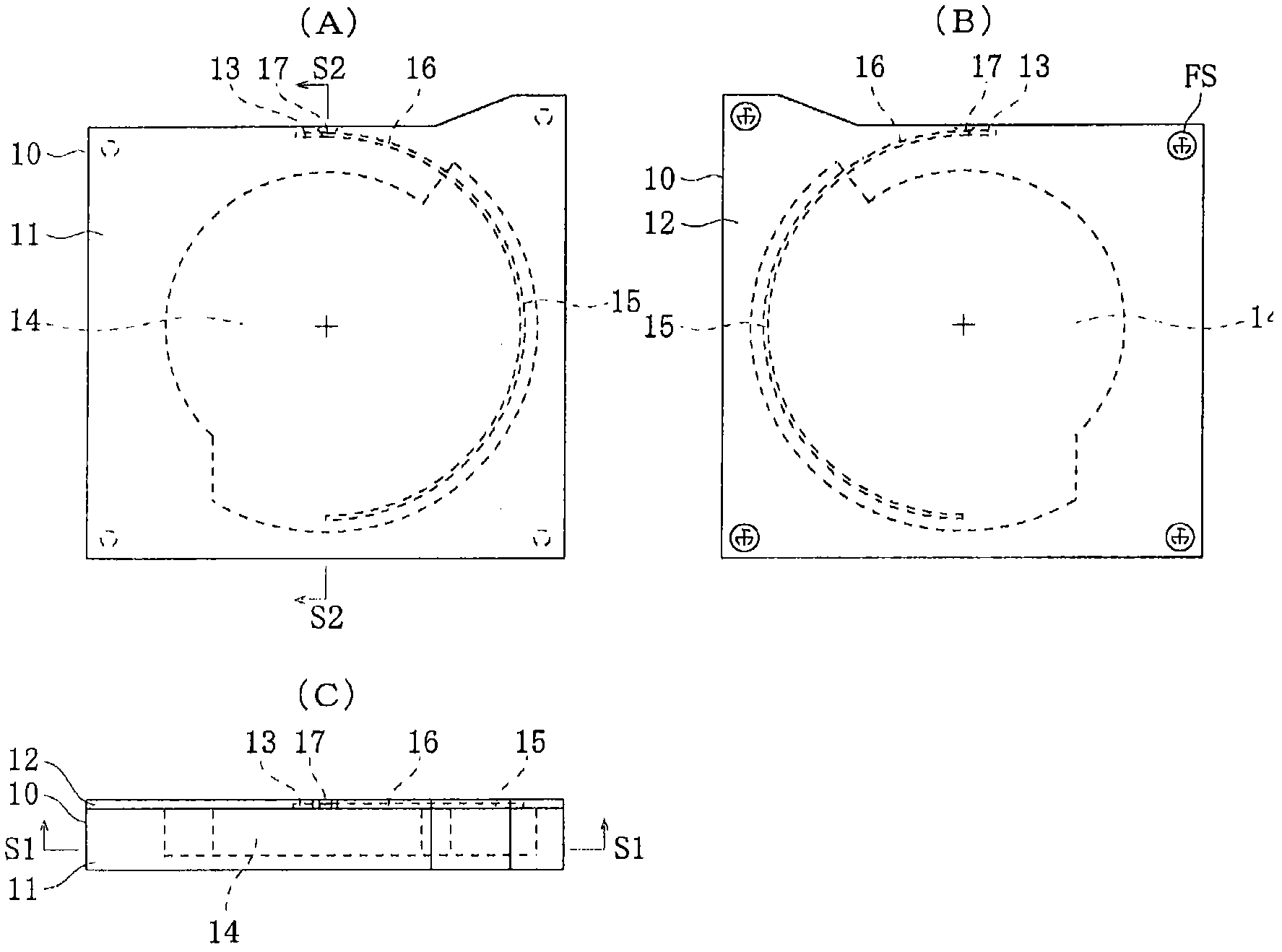
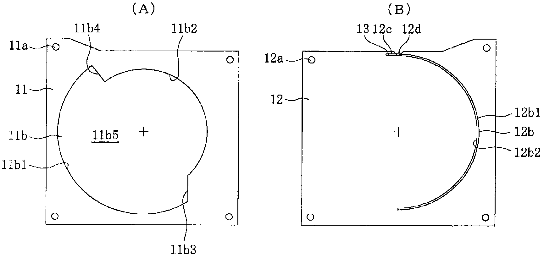
[0176] (Structure of Parts Storage Container (Second Embodiment))

[0177] Next, quote Figure 21 "The structure of the parts storage container (2nd embodiment)" is demonstrated. In this description, for ease of explanation, the Figure 21 The left, right, down, up, near front, and inside are called front, back, left, right, up, and down, respectively.

[0178] Figure 21 The illustrated parts storage container 10-1 differs from the above-described parts storage container 10 in that:

[0179] - A magnetizable stopper 13 - 1 is used as the stopper 13 .

[0180] The stopper 13-1 can be magnetized by the magnetic force of the permanent magnet 22c of the rotor 22, specifically, a rod made of a ferromagnetic material such as iron or nickel, or a bar made of a ferromagnetic material. A rod material in which a layer composed of another material belonging to a ferromagnetic body is formed by electroplating or the like on the entire surface of the base material, or a bar material ...

no. 3 approach

[0194] (Structure of Parts Storage Container (Third Embodiment))

[0195] Next, quote Figure 22 and Figure 23 , and "the structure of the parts storage container (third embodiment)" will be described. In the description, for the sake of illustration, the Figure 22 The left, right, lower, upper, near front, and inside are respectively called front, back, left, right, upper, and lower, and the same name Figure 23 directions comparable to these directions.

[0196] Figure 22 and Figure 23 The illustrated parts storage container 10-2 differs from the above-described parts storage container 10 in that:

[0197] - An elastically deformable shutter 18 that opens and closes the take-out port 17 when the rotor 22-1 operates is added.

[0198] The shutter 18 integrally has: a fixed part 18a; an elastic part 18b continuous with the fixed part 18a; an arm part 18c continuous with the elastic part 18b; The closing part 18d; the pushed part 18e provided at the front end of the...


PUM


Abstract

Provided is a bulk feeder parts holding case such that desired "parts replenishment work" and "parts changing work" can be appropriately performed through simple replacement work, and that even after replacement, the original functions of a bulk feeder can be demonstrated without hindrance. A parts holding case (10) has non-common elements which change according to the sizes and shapes of parts. The parts holding case (10) can be removably mounted on a feeder body (20) which has common elements that do not change according to the sizes and shapes of parts. Therefore, even if a parts holding case (10) which is mounted on the feeder body (20) is replaced with another parts holding case (10), a parts supply operation similar to one prior to replacement can be achieved, irrespective of types of parts.

Description

technical field [0001] The present invention relates to a component storage container for a bulk material feeder which can be detachably attached to a feeder main body and used. Background technique [0002] One structural example of the bulk material feeder is disclosed by patent document 1 and patent document 2. In detail, the disclosed bulk feeder includes: a storage chamber with a rear wall surface and an arc-shaped guide surface on the periphery; an inlet (hereinafter referred to as the inlet) located at the upper end of the guide surface; A passage provided toward the downstream; a component separation part provided at the front end of the passage; a rotating plate provided behind the wall surface of the storage chamber; and a plurality of magnets provided on the rotating board. [0003] This bulk feeder has a function of simultaneously attracting the components in the storage chamber by the magnetic force of the magnets by rotating the rotary plate in a predetermined...

Claims


Application Information

Patent Timeline
Patent Type & Authority Applications(China)
IPC IPC(8): B65G47/14H05K13/02
CPCB65G47/1442B65G47/14H05K13/02
Inventor 齐藤浩二
Owner TAIYO YUDEN KK
Why Eureka
Try Eureka