Disintegrating device

A technology of crushing device and screening device, applied in grain processing and other directions, can solve the problems of inability to guarantee, easy to reach the drum, etc., and achieve the effect of increasing the scope and opportunity

Inactive Publication Date: 2015-06-10
杜特史塔特费莫联股份有限公司
View PDF9 Cites 8 Cited by
  • Summary
  • Abstract
  • Description
  • Claims
  • Application Information

AI Technical Summary

Problems solved by technology

However, this does not guarantee easy access to the rollers, especially on bottoms that cannot be seen or touched

Method used


Image

  • Disintegrating device
  • Disintegrating device
  • Disintegrating device

Examples


Embodiment Construction

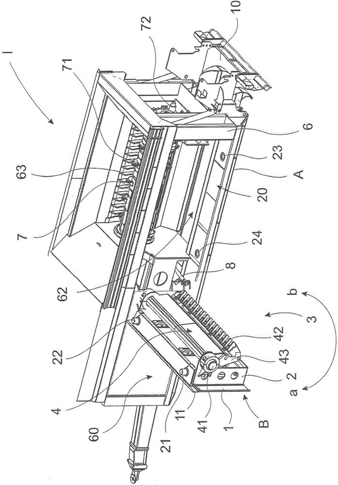
[0028] Figure 1aA schematic diagram showing a crushing device I according to the present invention without a screening device and when the common component B is in an outwardly pivoted position. The pulverizing device I and the common component B are each represented by an arrow. The casing 6 is mounted on a mounting surface A on the ground and / or a mounting plane, which is not shown in detail here. The mounting surface A is visible from the casing 6 in an upward direction. The common component B includes the wall 61 and / or the wall 60 that are part of the casing 6 . The non-pivotable part of the wall of the cabinet is referred to as the wall 60 . The pivotable common assembly B comprises a frame 2, such as Figure 1a As shown, the frame 2 is inserted into a part of the wall 61 through a guide 11 . A comb-shaped carrier 4 is disposed on the frame 2 , and a plurality of corresponding blades 42 are disposed on the comb-shaped carrier 4 . In addition, a comb carrier shaft 41...


PUM


Abstract

The invention relates to a disintegrating device, comprising a machine housing (6), which can be installed on an installation plane or an installation surface (A), and at least one disintegrating roller (7). The disintegrating rollers is rotatably supported in the machine housing (6) and has at least one disintegrating tool (71) arranged thereon, at least one counter blade (42), which interacts with the disintegrating tool (71), and at least one comb carrier (4) on at least one wall (61) of the machine frame (6) extending parallel to the axis of rotation (72) of the disintegrating roller (7). The invention is characterized in that at least part of the wall (61) of the machine housing (6) forms a common, in particular pivotable assembly (B) together with the comb carrier (4).

Description

technical field [0001] The invention relates to a comminution device comprising at least one comminution drum, rotatably supported in a casing, on which is placed at least one comminution tool interacting with at least one corresponding blade, and at least one comb A comb-shaped carrier is arranged on at least one wall of the casing, and the comb-shaped carrier extends in a direction parallel to the rotation axis of the crushing drum. Background technique [0002] Such comminuting devices are sufficiently known to the state of the art, for example according to the above-cited DE 83 31 826 U1, DE 20 2006 006 802 U1, and WO 2010 / 032 037 A1. The inaccessibility of the crushing drums is a problem when it comes to cleaning and maintenance, especially when the crushing tools need to be changed. Maintenance personnel often have to lean over into the housing from above and rotate the shredding tool accordingly to gain access to the shredding tool. If the tool and / or the correspond...

Claims


Application Information

Patent Timeline
Patent Type & Authority Applications(China)
IPC IPC(8): B02C18/14B02C18/18B02C18/16
CPCB02C18/145B02C18/20B02C2018/162B02C2018/188B02C18/14B02C18/146B02C18/16B02C18/18
Inventor 约翰·杜特史塔特霍斯特·贝格尔
Owner 杜特史塔特费莫联股份有限公司
Why Eureka
Try Eureka