Supercharge Your Innovation With Domain-Expert AI Agents!

Turbo compressor and compressor system comprising said turbo compressor

A technology of turbo compressors and compressors, which is applied to mechanical equipment, gas turbine devices, machines/engines, etc. It can solve the problems of entering the environment, the load of dust on the drive motor, and the entry of impurities to achieve effective cooling.

Active Publication Date: 2012-10-03
KAESER KOMPRESSOREN SE
View PDF11 Cites 5 Cited by
  • Summary
  • Abstract
  • Description
  • Claims
  • Application Information

AI Technical Summary

Problems solved by technology

[0004] However, this results in a considerable load of dust on the drive motor and, on the other hand, the problem that unwanted impurities are carried into the drive motor and into the environment.

Method used


Image

  • Turbo compressor and compressor system comprising said turbo compressor
  • Turbo compressor and compressor system comprising said turbo compressor
  • Turbo compressor and compressor system comprising said turbo compressor

Examples


Embodiment Construction

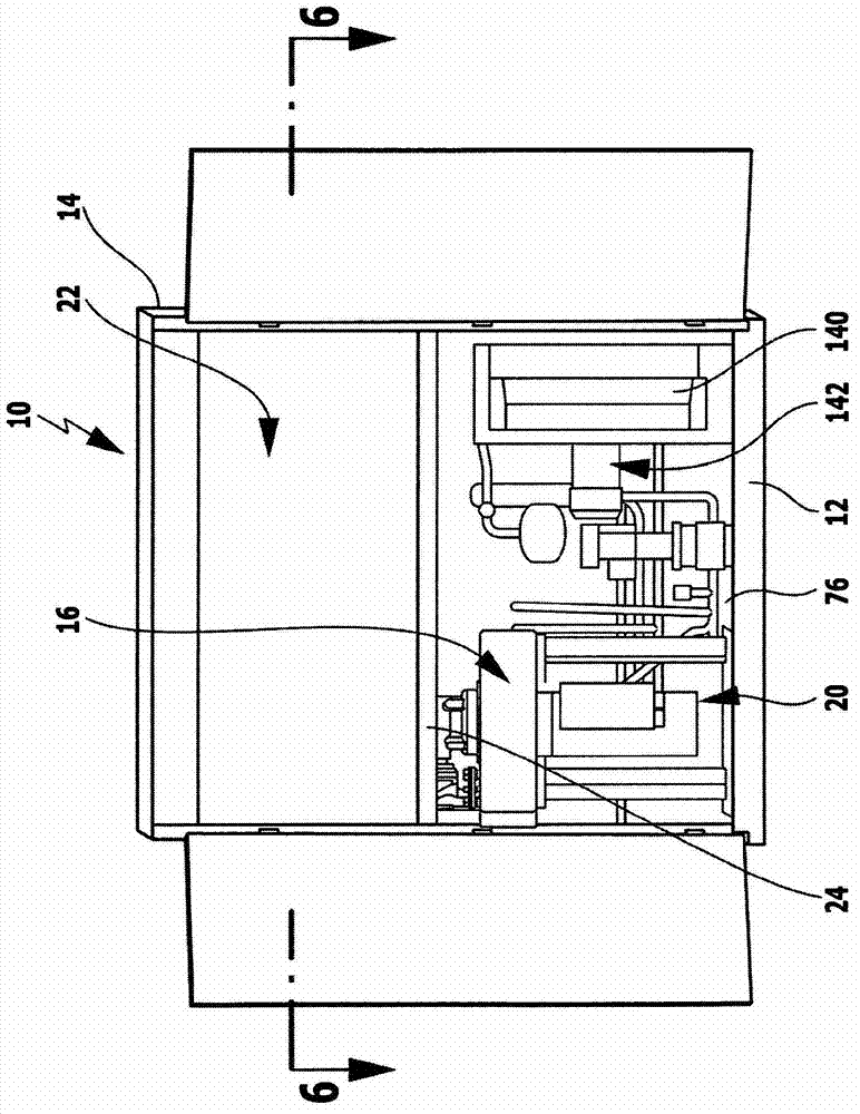
[0065] According to the compressor device of the present invention figure 1 The embodiment shown in includes a device housing, generally designated by the reference numeral 10 , which includes a housing cover 14 raised above a housing bottom 12 .

[0066] Mounted on the housing bottom 12 is a holding unit 16 , which accommodates a turbocompressor designated overall by the reference number 20 .

[0067] The turbo compressor 20 is used to compress air, the turbo compressor 20 sucks in air via an intake module 22 , which is connected to the compressor 20 via a compressor connection side 24 , and will be described in more detail below.

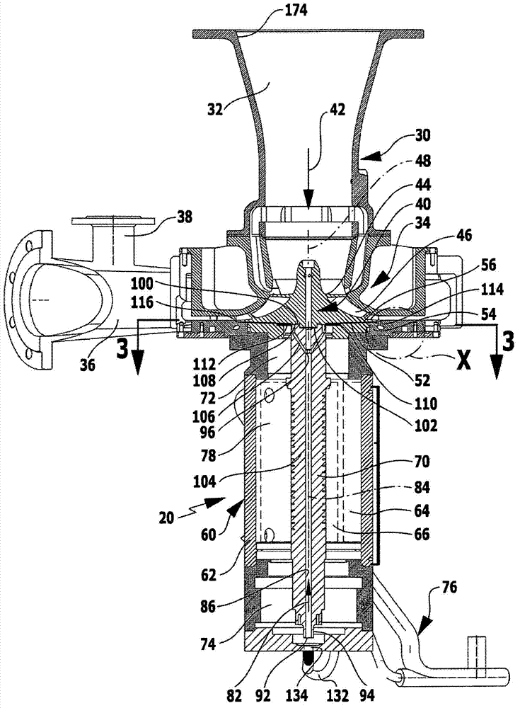
[0068] Such as figure 2 As shown, the turbocompressor 20 includes a compressor housing generally designated by the reference numeral 30, the compressor housing 30 includes a compressor inlet 32, an impeller housing 34, and a compressor outlet 36, wherein in the compressor outlet 36 A bypass branch 38 is provided.

[0069] Arranged in the impel...


PUM


Abstract

The invention relates to a turbo compressor for air which comprises a compressor housing and a bladed wheel arranged inside the compressor housing and a drive motor having a stator and a rotor on the rotor shaft of which the bladed wheel is arranged, In order to improve said turbo compressor such that the drive motor is optimally cooled, the drive motor is cooled by a closed cooling air circuit having a cooling air flow and the cooling air flow in said cooling air circuit flows through at least one cooling bore that extends through a section of the rotor shaft.

Description

technical field [0001] The invention relates to a turbocompressor for air, comprising a compressor housing and an impeller arranged in the compressor housing, as well as a drive motor with a stator and a rotor, the impeller being mounted on a rotor shaft of the rotor. Background technique [0002] Such turbocompressors are known from the prior art. [0003] In turbocompressors of this type, the drive motor is usually cooled in such a way that a flow of cooling air is blown over the drive motor. [0004] However, this results in a considerable load of dust on the drive motor and, on the other hand, the problem that unwanted impurities are entrained into the drive motor and into the environment. Contents of the invention [0005] It is therefore the object of the invention to improve the turbocompressor in such a way that the drive motor is cooled in an optimal manner. [0006] According to the invention, said object is solved in the turbocompressor according to the class ...

Claims


Application Information

Patent Timeline
Patent Type & Authority Applications(China)
IPC IPC(8): F04D25/06F04D29/42F04D29/58F04D29/66F02C7/045H02K9/10H02K9/197
CPCF04D29/584F01D5/088F01D5/085F04D25/0606H02K9/12F05D2260/96F04D29/664F04D29/4213F04D29/5806
Inventor 汉斯-约阿希姆·林乔尔·科菲·奥多马克
Owner KAESER KOMPRESSOREN SE
Features
  • R&D
  • Intellectual Property
  • Life Sciences
  • Materials
  • Tech Scout
  • Unparalleled Data Quality
  • Higher Quality Content
  • 60% Fewer Hallucinations
Learn More