

Gravity-type baffle device used at tail end of conveyer
A blocking device and gravity-type technology, applied in the field of conveying machinery, can solve the problems of high manufacturing and maintenance costs and complex structures, and achieve the effect of low manufacturing and maintenance costs and simple structure
- Summary
- Abstract
- Description
- Claims
- Application Information
AI Technical Summary
Problems solved by technology
Method used
Image

Examples
Embodiment Construction
[0017] The specific implementation manner of the present invention will be described below in conjunction with the accompanying drawings.
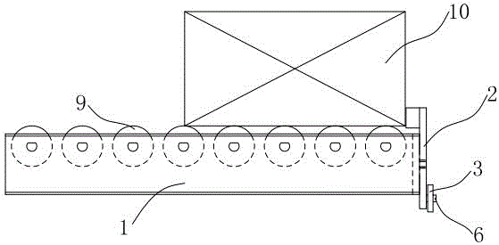
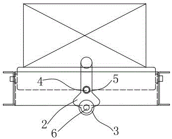
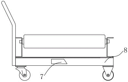
[0018] Such as figure 1 , figure 2 , image 3 , the present invention includes action block 7, blocking block 2, fixed shaft 4, fixed shaft 4 passes through mounting hole 5 on the blocking block 2 and is fixed on the frame 1, the aperture of mounting hole 5 is larger than the diameter of fixed shaft 4, blocks The block 2 can rotate and swing around the fixed shaft 4; one end of the blocking block 2 is equipped with a roller 3; one end of the roller 6 on the roller 3 is fixed on the blocking block 2; the function block 7 is installed on the left and right sides of the transport trolley; the installation hole 5 is located in the middle of the blocking block 2; the weight of one end of the blocking block 2 where the roller 3 is installed is greater than the weight of the other end of the blocking block 2; one end of the action block 7 is a...
PUM
 Abstract
Description
Claims
Application Information