
Driving device for switch operation interlocking mechanism

A technology of interlocking mechanism and driving device, applied in the direction of air switch components, etc., can solve problems such as large operating force, sliding teeth or mechanism deformation, interlock failure, etc., to achieve the effect of convenient operation and improved stability

Inactive Publication Date: 2012-10-10
江苏华冠电器集团有限公司
View PDF2 Cites 4 Cited by
  • Summary
  • Abstract
  • Description
  • Claims
  • Application Information

AI Technical Summary

Problems solved by technology

[0004] The current grounding operation interlock mechanism of the switchgear adopts a bevel gear transmission mechanism without a deceleration device, and the operating force is large, which is prone to slipping teeth or mechanism deformation, resulting in the failure of the grounding operation; the operating mechanism and the main shaft of the grounding switch must be on the same horizontal line, otherwise Unable to connect the transmission, lack of flexibility; the interlock mechanism is hard interlock, due to the large operating force, it is easy to damage the interlock parts, resulting in interlock failure; there is no mechanical position indication, and the grounding state is not clear; in this way, it is very easy to cause Accidents caused by faults such as misoperation, mechanism damage, and interlock failure

Method used


Image

  • Driving device for switch operation interlocking mechanism
  • Driving device for switch operation interlocking mechanism
  • Driving device for switch operation interlocking mechanism

Examples


Embodiment Construction

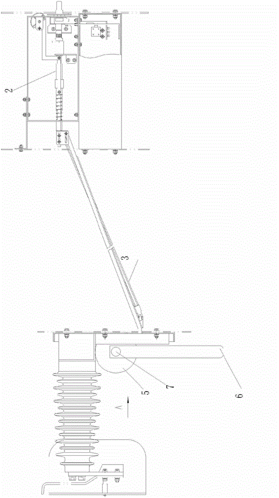
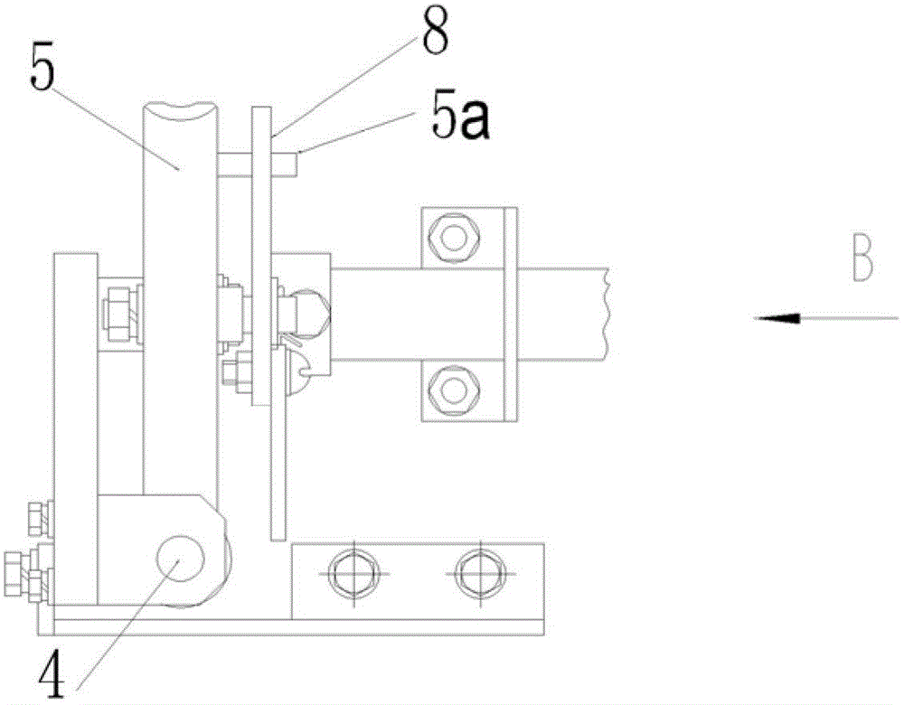
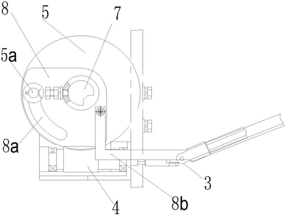
[0015] Such as figure 1 As shown, the drive device of the switch operation interlock mechanism, which includes a rotating mechanism located in the mechanism box 1, a worm wheel 5, a worm 4 and a stroke plate 8, the stroke plate 8 is fixed on the main shaft 7 of the grounding switch, and the main shaft 7 is connected to the grounding switch. The gate plate 6 on the grounding switch mechanism is connected, and the rotating mechanism is connected with the worm 4 through a universal joint. 5a is inserted into the stroke space 8a; wherein the rotating mechanism includes a rotating rod 2 and a transmission rod 3, the rotating rod 2 and the transmission rod 3 are connected through a transmission universal joint, and the transmission rod 3 is connected with the said worm 4 through the said universal joint ; Wherein, the stroke space 8a is an arc-shaped hollow groove on the stroke plate, and it can also be an arc-shaped guide groove.

[0016] Rotate the rotating rod 2, and then drive ...


PUM


Abstract

The invention belongs to the field of switch equipment, in particular to a switch operation interlocking mechanism. A driving device for the switch operation interlocking mechanism comprises a rotating mechanism arranged inside a mechanism box, a worm gear, a worm and a travel plate, wherein the travel plate is fixed on a spindle of a grounding switch; the rotating mechanism is connected with the worm by a universal joint; the worm is worked with the worm gear; a push rod is fixed on an end of the worm gear; and the travel plate is provided with a travel space, in which the push rod is inserted. The driving device for the switch operation interlocking mechanism has the advantages that the original bevel gear driving is replaced with the cooperated driving of the worm gear and worm, the operation of the rotating mechanism and the switching spindle of a flashboard can be performed at different positions, so that the operation is convenient; meanwhile, the phenomenon of gear sliding or mechanism deformation can be avoided, and the stability of the equipment is improved.

Description

technical field [0001] The invention belongs to the field of switch equipment, in particular to a switch operation interlocking mechanism. Background technique [0002] The operation interlock mechanism of the switchgear is one of the main components of the switch, and it is also the key part that is most prone to safety accidents, such as improper operation, mechanism deformation, interlock failure, etc., which are very prone to accidents such as personal electric shock, system short circuit, or even explosion. lead to widespread power outages. [0003] The function of the switch operation interlock mechanism is to close and open the grounding switch in the switch cabinet, and at the same time interlock with the circuit breaker in the switch cabinet to prevent the grounding switch from being charged and the grounding circuit breaker from being powered. , so as to ensure the safety of switchgear line inspection and maintenance, and prevent personal electric shock and system...

Claims


Application Information

Patent Timeline
Patent Type & Authority Applications(China)
IPC IPC(8): H01H31/04
Inventor 翁兴锋刘俊峰赵波薛忠郑云波陈建波谢永健
Owner 江苏华冠电器集团有限公司
Learn More