Supercharge Your Innovation With Domain-Expert AI Agents!

Direct mounted photovoltaic device with improved side clip

A photovoltaic device and clip technology, applied in heating devices, photovoltaic power generation, photovoltaic modules, etc., can solve the problem of BIPV not being activated

Inactive Publication Date: 2012-10-10
DOW GLOBAL TECH LLC
View PDF40 Cites 0 Cited by
  • Summary
  • Abstract
  • Description
  • Claims
  • Application Information

AI Technical Summary

Problems solved by technology

A particular issue related to ease of installation is the need to keep the BIPV inactive until needed (e.g. power generation)
Other potential issues involve alignment of adjacent solar installations, and potential packaging and shipping issues

Method used


Image

  • Direct mounted photovoltaic device with improved side clip
  • Direct mounted photovoltaic device with improved side clip
  • Direct mounted photovoltaic device with improved side clip

Examples


Embodiment Construction

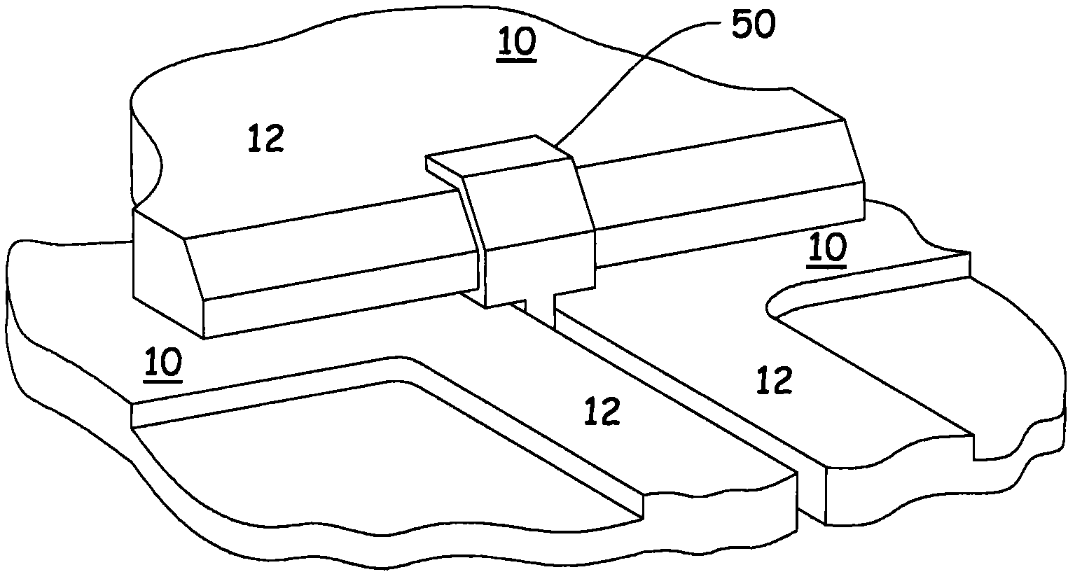
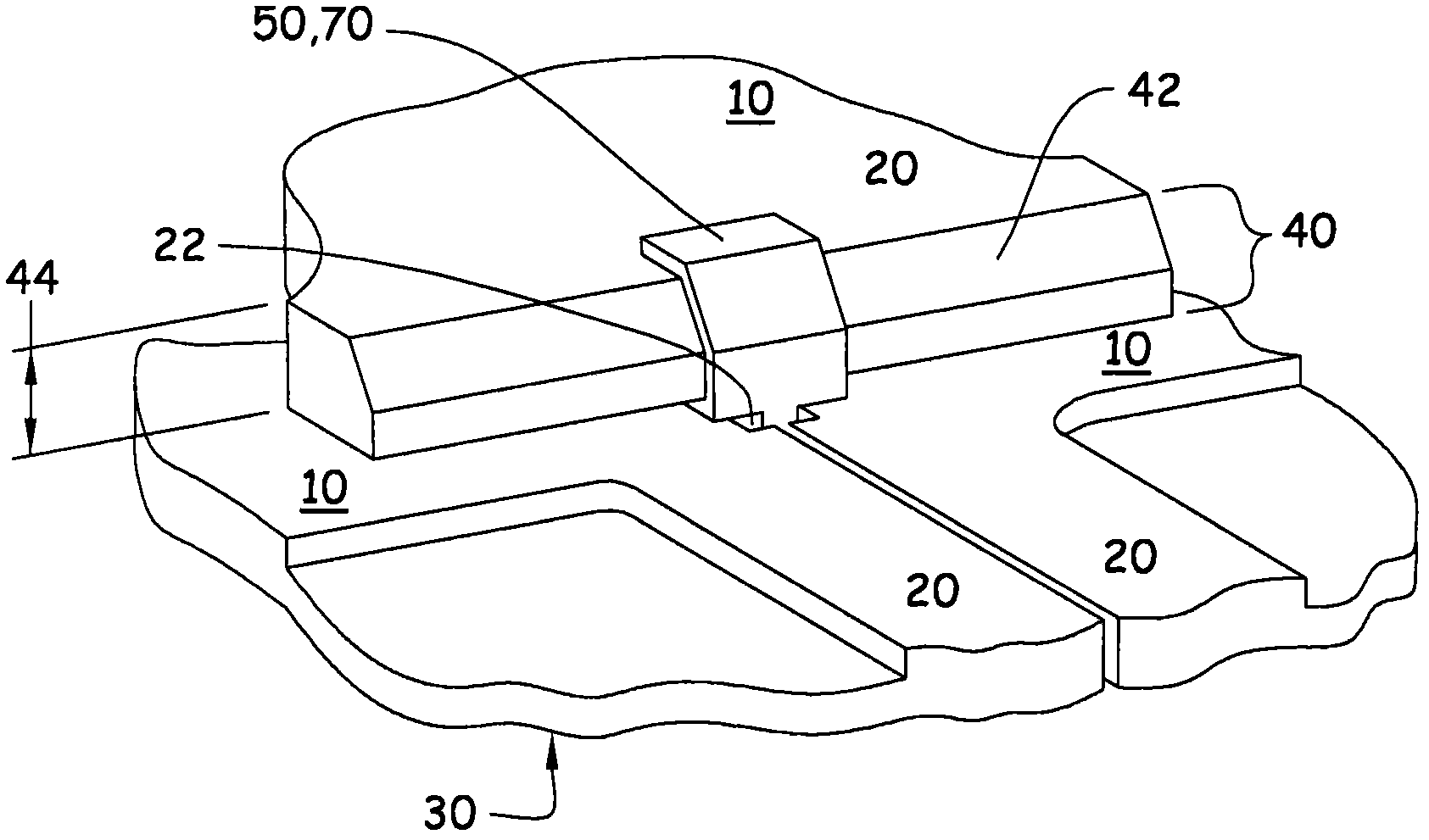
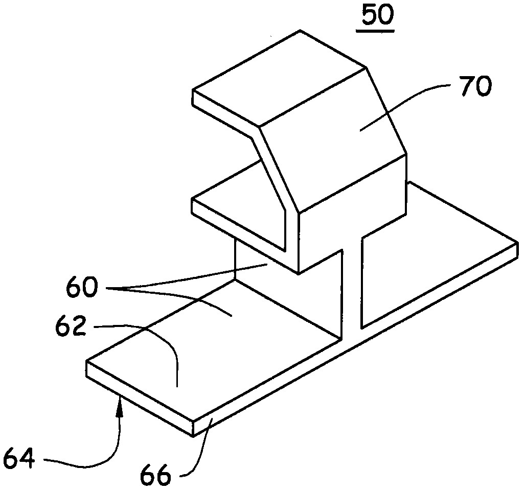
[0020] The present invention relates to a photovoltaic assembly system for securing and / or aligning at least a plurality of vertically adjacent (overlapping) photovoltaic device assemblies 10 (or overlapping photovoltaic device arrays) to each other. The device 10 is preferably mounted directly to a structure (eg, a building structure, wall and / or roof deck). The present invention seeks to overcome the wind-uplifting problem through a unique clip solution, and optionally utilize this solution to address some of the other potential problems previously discussed. figure 1 Three photovoltaic devices 10 are shown in an assembled configuration (eg, a lower photovoltaic device array comprising two horizontally adjacent devices 10 and an overlapping upper photovoltaic device array comprising one device 10 ). Figures 1 to 6 Other detailed views of the device and / or clip are shown.

[0021] Photovoltaic installation

[0022] In general, the photovoltaic device ("photovoltaic device mo...


PUM


Abstract

The present invention is premised upon a photovoltaic assembly system for securing and / or aligning at least a plurality of vertically adjacent photovoltaic device assemblies to one another. The securing function being accomplished by a clip member that may be a separate component or integral to one or more of the photovoltaic device assemblies.

Description

[0001] This invention was made with US Government support under Contract No. DE-FC36-07G017054, Department of Energy. The US Government has certain rights in this invention. [0002] priority statement [0003] This application claims the benefit of the filing date of US Provisional Application No. 61 / 253,978 (filed October 22, 2009), the contents of which are hereby incorporated by reference in their entirety. technical field [0004] The present invention relates to photovoltaic devices mounted directly to structures and methods thereof, and more particularly to photovoltaic shingles capable of being mounted directly to building structures such as roof decks or walls and methods thereof. Background technique [0005] Efforts to improve the state of the art in the field of solar power generation, particularly building-mounted power generation, have received growing industry attention in recent years. Building-integrated photovoltaics (BIPV) are a subset of building-mounte...

Claims


Application Information

Patent Timeline
Patent Type & Authority Applications(China)
IPC IPC(8): F24J2/52H01L31/042H01L31/048
CPCY02B10/20F24J2002/0061F24J2/5247F24J2002/4665Y02E10/50H01L31/0422Y02B10/12Y02E10/47F24S25/613F24S2020/13F24S2025/6004H02S20/22H02S20/23Y02B10/10
Inventor J·R·基尼汉M·L·伯文C·布朗G·K·厄里奇R·S·加斯顿M·休斯
Owner DOW GLOBAL TECH LLC
Features
  • R&D
  • Intellectual Property
  • Life Sciences
  • Materials
  • Tech Scout
  • Unparalleled Data Quality
  • Higher Quality Content
  • 60% Fewer Hallucinations
Learn More