
Image forming apparatus, image forming method, and computer readable medium

An image and ejection position technology, applied in the direction of printing device, printing, etc., can solve the problem of consuming pre-ejection ink, etc., and achieve the effect of suppressing ink waste, preventing clogging, and preventing the decline of printing quality

Active Publication Date: 2012-10-17
FUJIFILM BUSINESS INNOVATION CORP
View PDF10 Cites 5 Cited by
  • Summary
  • Abstract
  • Description
  • Claims
  • Application Information

AI Technical Summary

Problems solved by technology

[0005] However, since full ejection (100% density) of inks of all colors (Y, M, C, and K) is performed on the inter-page boundary over the entire width of the paper (in the direction perpendicular to the paper conveyance direction) during the pre-ejection , so the method involves a large consumption of pre-jet ink

Method used


Image

  • Image forming apparatus, image forming method, and computer readable medium
  • Image forming apparatus, image forming method, and computer readable medium
  • Image forming apparatus, image forming method, and computer readable medium

Examples


Embodiment approach

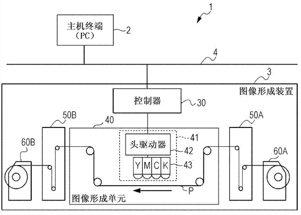
[0039] figure 1 is a diagram showing an exemplary schematic configuration of an image forming system 1 according to an exemplary embodiment of the present invention.

[0040] In the image forming system 1, a host terminal 2 such as a personal computer (PC) and an image forming apparatus 3 that performs printing with continuous paper P at high speed are connected to each other via a network 4 such as a local area network (LAN).

[0041] The image forming apparatus 3 is a printing apparatus that prints a print job (eg, a document) on continuous paper P at high speed in response to a print instruction supplied from the host terminal 2 , and includes a recording head 41 of a full line inkjet method.

[0042] The full line inkjet method is a method of performing printing by fixing the recording head in place, and by moving a continuous sheet of paper toward the recording head in a certain direction.

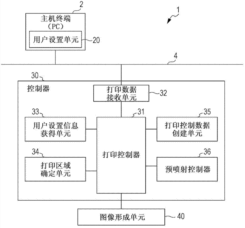
[0043] The image forming apparatus 3 includes a controller 30, an image forming ...


PUM


Abstract

An image forming apparatus includes an ink-ejecting unit, a region dividing unit, and a preparatory ejection unit. The ink-ejecting unit has a recording head aligned in a width direction which is substantially perpendicular to a transport direction of a recording sheet, and ejects ink onto the recording sheet through plural orifices of the recording head in accordance with print data to be printed in response to a print instruction, thereby printing an image. The region dividing unit divides, in the width direction of the recording sheet, a print region of the recording sheet into a user region and a print control region. The preparatory ejection unit preparatorily ejects ink onto the recording sheet through the plural orifices so that an amount of ink ejected through an orifice for the print control region is smaller than an amount of ink ejected through an orifice for the user region.

Description

technical field [0001] The present invention relates to an image forming apparatus and an image forming method for effectively preventing clogging of ink jet nozzles in a full-line recording head provided in an ink jet printing apparatus. Background technique [0002] In the ink jet printing apparatus, if the ink jet nozzles provided in the full-line recording head do not perform ink jetting for a long time, clogging may occur in the nozzles, which will lower the printing quality. [0003] In order to prevent such troubles, Japanese Unexamined Patent Application Publication No. 2002-225301 proposes a pre-ejection technique for periodically cleaning the nozzles of the recording head. [0004] Likewise, the method for pre-inking to the interpage boundary of continuous paper can be used as a method for preventing clogging of the inkjet nozzles of the inkjet printing apparatus. [0005] However, since full ejection (100% density) of ink of all colors (Y, M, C, and K) is perform...

Claims


Application Information

Patent Timeline
IPC IPC(8): B41J2/01B41J2/165B41J29/38
CPCB41J2/16585B41J2/16526
Inventor 驹沢寿夫川端喜荣
Owner FUJIFILM BUSINESS INNOVATION CORP
Learn More