
Adhesive composition and optical member using the same

A technology for optical components and adhesives, applied in the directions of optical components, non-polymer adhesive additives, adhesive types, etc., can solve the problems of reduced durability, poor initial bonding strength, etc., and achieve excellent creep performance , excellent bonding strength, excellent anti-leakage effect

Active Publication Date: 2012-10-17
CHEIL IND INC
View PDF2 Cites 0 Cited by
  • Summary
  • Abstract
  • Description
  • Claims
  • Application Information

AI Technical Summary

Problems solved by technology

However, hard type adhesives for polarizing plates have poor initial bond strength due to storage modulus (G'), and thus durability is significantly reduced

Method used


Image

  • Adhesive composition and optical member using the same
  • Adhesive composition and optical member using the same
  • Adhesive composition and optical member using the same

Examples


Embodiment 1 to 4

[0080] The above components were mixed according to the compositions listed in Table 1, and to the mixture was added 20 parts by weight of methyl ethyl ketone as a diluent, and uniformly stirred for 20 minutes, thereby preparing a coating solution. The adhesive coating solution was deposited on a release film to a dry thickness of 25 μm to prepare an adhesive sheet, followed by aging at 35° C. and 45% RH. Then, the properties of the adhesive were evaluated.


PUM


Abstract

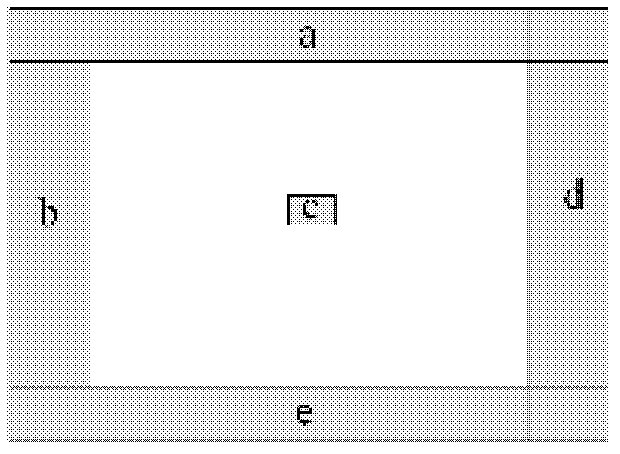
The invention discloses an adhesive composition and an optical member using the same. The adhesive composition has an excellent production rate and the excellent anti-light leakage property as a hard adhesive composition without additional procedures. The adhesive composition also has the surface resistance of 108 to 1012 angstrom / sq, and the difference in brightness ([Delta]L) between an edge part and a center part. The difference is calculated by the formula of [Delta]L = [(a+b+d+e) / 4]-c and is higher than 0 and is less than 1. In the formula, each of a, b, d, and e is the average luminance on site corresponding the 1 / 16 of total surface from an end part of each side of an optical element, and c is the average luminance of 1 / 32 of the surface of a center part in the optical element.

Description

technical field [0001] The present invention relates to an adhesive and an optical element using the same. More specifically, the present invention relates to an adhesive having improved transparency, durability, and antistatic performance while maintaining excellent productivity and light leakage resistance which are advantages as a hard type adhesive, and an optical device using the same. element. Background technique [0002] Optical films include polarizing plates, color filters, phase retardation films, elliptically polarizing films, reflective films, antireflection films, compensation films, brightness enhancement films, orientation films, light diffusion films, Glass anti-scattering film, surface protection film, plastic LCD substrate, etc. [0003] When an optical element such as a polarizing plate or a phase retardation film is stacked on a liquid crystal cell to manufacture an LCD, a bonding method using an adhesive layer is preferable. Since a release film or a...

Claims


Application Information

Patent Timeline
IPC IPC(8): C09J11/06C09J133/08C09J133/10G02B1/10
CPCC09J7/22C09J7/385C09J9/00C09J11/06C09J133/04C09J2203/318C09J2301/302C09J2301/312C09J2301/408
Inventor 郑丽娜郑喆郑宇镇
Owner CHEIL IND INC
Learn More