Rotary type compressor

A technology of rotary compressors and compression mechanisms, which is applied to rotary piston/oscillating piston pump components, mechanical equipment, machines/engines, etc., and can solve problems such as temperature rise of lower stator windings

Inactive Publication Date: 2012-10-17
EMERSON CLIMATE TECH INC
View PDF5 Cites 5 Cited by
  • Summary
  • Abstract
  • Description
  • Claims
  • Application Information

AI Technical Summary

Problems solved by technology

In such a case, the temperature rise problem of the lower stator winding will be more serious

Method used


Image

  • Rotary type compressor
  • Rotary type compressor
  • Rotary type compressor

Examples


Embodiment Construction

[0034] Exemplary embodiments of the present invention will be described below with reference to the accompanying drawings. In the interest of clarity and conciseness, not all features of an actual implementation are described in this specification. It should be understood, however, that in developing any such practical embodiment, many implementation-specific decisions must be made in order to achieve the developer's specific goals, such as meeting those constraints related to the system and business, and those Restrictions may vary from implementation to implementation. Moreover, it should also be understood that development work, while potentially complex and time-consuming, would at least be a routine undertaking for those skilled in the art having the benefit of this disclosure.

[0035] Here, it should also be noted that, in order to avoid obscuring the present invention due to unnecessary details, only some device structures and / or processing steps related to the soluti...


PUM


Abstract

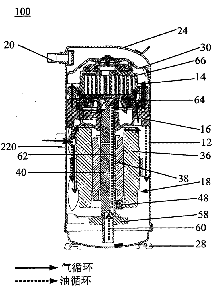
The invention discloses a rotary type compressor. The rotary type compressor comprises a casing, a compression mechanism arranged in the casing, a driving mechanism arranged in the casing and cooperated with the compression mechanism for driving the compression mechanism, wherein the driving mechanism comprises a stator fixed to the casing, a rotor positioned in the stator and a driving shaft connected to the rotor, wherein a first eccentric channel and a second eccentric channel are provided in the driving shaft, the first eccentric channel is configured that when the driving shaft is rotated, the oil positioned at the lower part of the casing can be transferred to the compression mechanism, and the second eccentric channel possesses an oil injection hole, and is configured that when the driving shaft is rotated, oil is injected through the oil injection hole to the lower stator winding on the stator.

Description

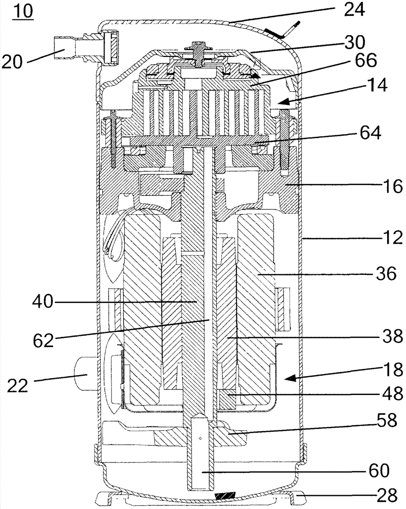
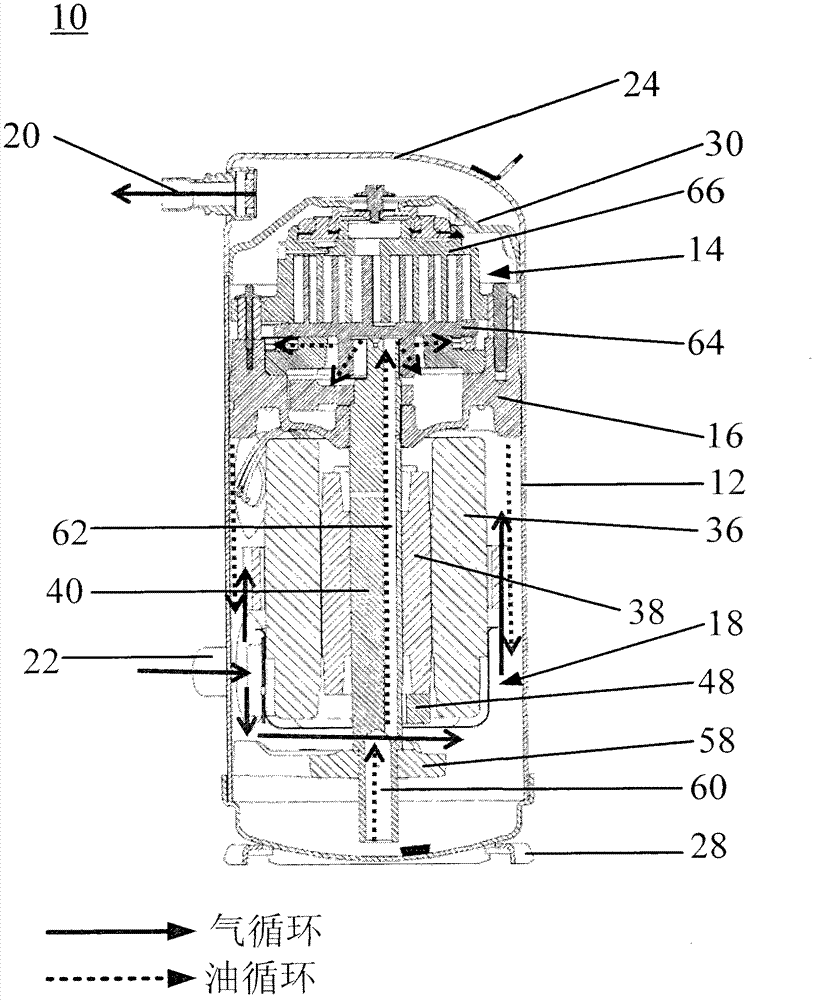
technical field [0001] The present invention relates to a rotary compressor. Background technique [0002] In air conditioning and refrigeration applications, rotary refrigeration compressors are usually equipped with low suction ports such as figure 1 shown. When the rotary compressor 10 is working, the inhaled gas will enter the interior of the casing 12 through the air inlet joint 22 located at the lower part of the casing 12 . A portion of the gas will enter the drive mechanism 18 to cool the upper and lower stator windings wound on the stator 36 . However, most of the gas will rise and enter the compression mechanism 14 . The gas will pass over the oil sump at the bottom of the housing 12 and mix with the splashed oil droplets. Significant amounts of oil can be carried away by the gas, challenging the oil circulation rate. Especially in the case of parallel application of multiple compressors, or in the case of flood back, when the oil level goes high, it often res...

Claims


Application Information

Patent Timeline
Patent Type & Authority Applications(China)
IPC IPC(8): F04C29/02F04C29/04
Inventor 韩艳春郑瑞敏
Owner EMERSON CLIMATE TECH INC
Why Eureka
Try Eureka