Natural heat dissipating layout of electrical or electronic heating device

A heat-generating device and natural heat dissipation technology, applied in the direction of cooling/ventilation/heating transformation, etc., can solve problems such as unreasonable layout of power modules and temperature rise

Inactive Publication Date: 2016-01-27
TBEA XIAN ELECTRIC TECH +1
View PDF4 Cites 0 Cited by
  • Summary
  • Abstract
  • Description
  • Claims
  • Application Information

AI Technical Summary

Problems solved by technology

[0004] In order to overcome the above-mentioned problems in the prior art, the purpose of the present invention is to provide a natural heat dissipation layout of power electronic heating devices, which solves the problem of temperature rise caused by the unreasonable layout position of the power module on the radiator

Method used


Image

  • Natural heat dissipating layout of electrical or electronic heating device
  • Natural heat dissipating layout of electrical or electronic heating device
  • Natural heat dissipating layout of electrical or electronic heating device

Examples


Embodiment

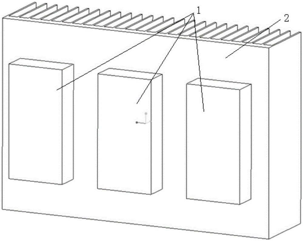
[0016] The three heat source power modules dissipate heat through the natural cooling radiator. The length, width and height of the radiator are 40*520*110mm, the length, width and height of the heat source power module are 66*32*10mm, and the heat loss is 108W.

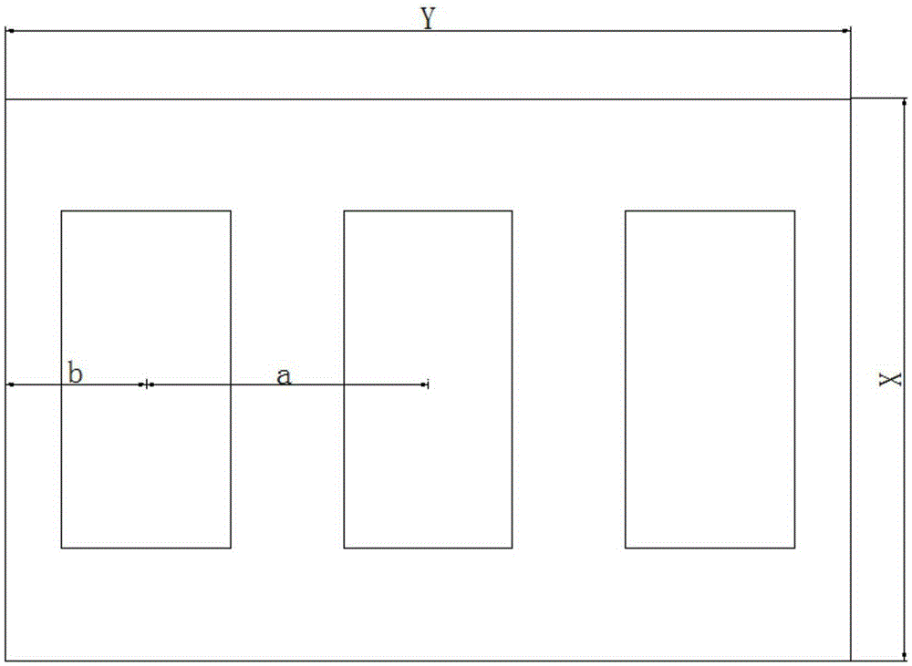
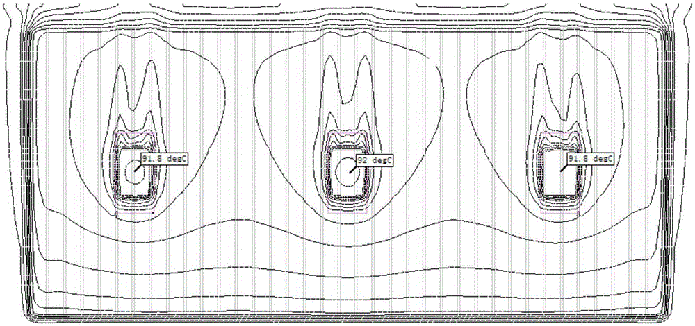
[0017] 1. When the layout of the heat source power module meets the layout requirements of the present invention, that is, a=520 / 3, b=520 / 6: the temperature isotherm diagram of the heat source is obtained through the simulation software, such as image 3 Shown: The maximum temperature of the heat source power module is 92 degrees Celsius, and the temperature difference between the three heat source power modules is 0.2 degrees Celsius.

[0018] 2. When the layout of the heat source power module does not meet the design requirements of the present invention:

[0019] The first case: if a>520 / 3b Figure 4 Shown: The maximum temperature of the heat source power module is 93 degrees Celsius, and the temperature difference...


PUM


Abstract

A natural heat dissipating layout of an electrical or electronic heating device dissipates heat in a natural cooling way. The layout comprises a heater and one or more main heat source power modules installed on the back surface of a flow channel of the heater. The layout positions of the main heat source power modules on the heater satisfy the following requirements: when the length of the heater along the flow channel direction is X and the width is Y and the number of the main heat source power modules is N, the distance between two geometrical centers of contact surfaces of any two adjacent main heat source power modules and the heater is a = Y / N, and the distance between each main heat source power module on the edge and the edge along the widthwise direction of the heater is b = Y / 2N; and when the number of the main heat source power module is one, the geometrical center of the contact surface of the main heat source power module and the heater coincides with the geometrical center of a base board surface of the heater. The layout solves the problem that unreasonable layout positions of power modules on a heater cause temperature rises.

Description

technical field [0001] The invention relates to the technical field of power electronic equipment, in particular to a natural heat dissipation layout of a power electronic heating device. Background technique [0002] For electrical equipment, there are generally key heating components, especially the core module, which generates a huge amount of heat. It is necessary to design a separate radiator to dissipate the heat inside the electrical equipment as soon as possible to ensure stable and reliable operation of the equipment. Considering some other factors in the prior art, there are products that use natural cooling to dissipate heat, such as photovoltaic inverters. This product directly installs its main heating element, the power module, on the radiator to dissipate heat. During the installation process, due to Some other factors, such as the size of the PCB, the impact of the screw hole position of the structural parts, and the layout position of the main heat-generatin...

Claims


Application Information

Patent Timeline
IPC IPC(8): H05K7/20
Inventor 陈伟杨雄鹏郑超
Owner TBEA XIAN ELECTRIC TECH
Why Eureka
Try Eureka