Overflow valve

A relief valve and spool technology, which is applied in the direction of fluid pressure actuators, servo motor components, mechanical equipment, etc., can solve the problems of poor reliability and short service life of relief valves

Active Publication Date: 2012-10-17
浙江高宇液压机电有限公司
View PDF10 Cites 4 Cited by
  • Summary
  • Abstract
  • Description
  • Claims
  • Application Information

AI Technical Summary

Problems solved by technology

[0005] The purpose of the present invention is to provide an overflow valve to solve

Method used


Image

  • Overflow valve
  • Overflow valve

Examples


Embodiment Construction

[0039] In order to further explain the technical solution of the present invention, the present invention will be described in detail below through specific examples.

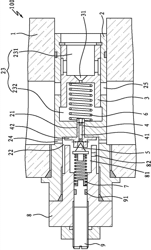
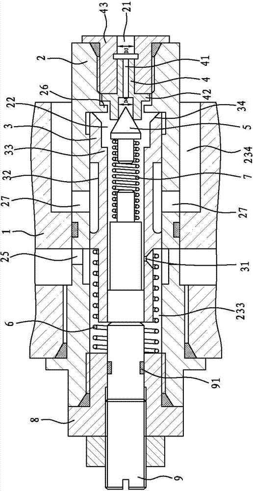
[0040] like figure 1 As shown, it is the first embodiment of a relief valve 100 according to the present invention. The relief valve 100 includes a valve body 1, a main valve seat 2, a main valve core 3, a pilot valve seat 4, a pilot valve core 5, The main valve spring 6, the pilot valve spring 7 and the gland 8, the main valve seat 2 is fixedly sleeved in the valve body 1, the above structure is basically the same as the structure principle of the traditional pilot relief valve, so no detailed description will be given.

[0041] The key improvement of the present invention is: the relief valve 100 also includes a pilot valve seat installation hole 21 and a pilot valve seat limit portion, the pilot valve seat 4 is movably sleeved in the pilot valve seat installation hole 21, the pilot valve seat 4 A pilot valv...


PUM


Abstract

The invention discloses an overflow valve comprising a valve body, a main valve seat, a main valve core, a pilot valve seat, a pilot valve core, a main valve spring, a pilot valve spring, a pilot valve seat installation hole and a pilot valve seat limit part, wherein the main valve seat is fixedly sleeved in the valve body, and the pilot valve seat is movably sleeved in the pilot valve seat installation hole and is provided with a pilot valve oil inlet; and the pilot valve seat limit part is used for limiting the motion range of the pilot valve seat, so that the motion stroke of the pilot valve seat is shorter than that of the pilot valve core. Compared with the prior art, with the adoption of the overflow valve, abrasion of the pilot valve core and the pilot valve seat is small, and the pre-pressure of the pilot valve spring is small, so that the using reliability of the overflow valve can be greatly improved, and the service life of the overflow valve can be greatly prolonged.

Description

technical field [0001] The invention relates to the field of valve body structure, and more specifically relates to an overflow valve, which has the characteristics of high reliability and long service life. Background technique [0002] The relief valve is generally used in hydraulic equipment, and mainly plays the role of constant pressure relief, pressure stabilization, system unloading and safety protection. An existing pilot-operated relief valve includes a valve body, a main valve seat, a main valve core, a pilot valve seat, a pilot valve core, a main valve spring and a pilot valve spring, and the pressure oil in the working chamber enters through a damping hole. To the front chamber of the pilot valve, when the working pressure is greater than the opening pressure set by the pilot valve, the pilot valve will open, and the hydraulic oil in the oil inlet chamber of the main valve will flow through the orifice, the oil inlet chamber of the pilot valve, and flow back to t...

Claims


Application Information

Patent Timeline
IPC IPC(8): F15B13/02
Inventor 严光贤
Owner 浙江高宇液压机电有限公司
Why Eureka
Try Eureka