Check patentability & draft patents in minutes with Patsnap Eureka AI!

Optical touch screen system

An optical touch and screen technology, applied in the direction of instruments, electrical digital data processing, input/output process of data processing, etc., can solve problems such as wrong coordinates, inconvenient application, easy to reduce accuracy, etc.

Inactive Publication Date: 2012-10-17
PIXART IMAGING INC
View PDF3 Cites 8 Cited by
  • Summary
  • Abstract
  • Description
  • Claims
  • Application Information

AI Technical Summary

Problems solved by technology

However, for more than two contact objects, the images often reduce the accuracy of coordinate estimation or get wrong coordinates (ghost images) due to occlusion, causing inconvenience in application

Method used


Image

  • Optical touch screen system
  • Optical touch screen system
  • Optical touch screen system

Examples


Embodiment Construction

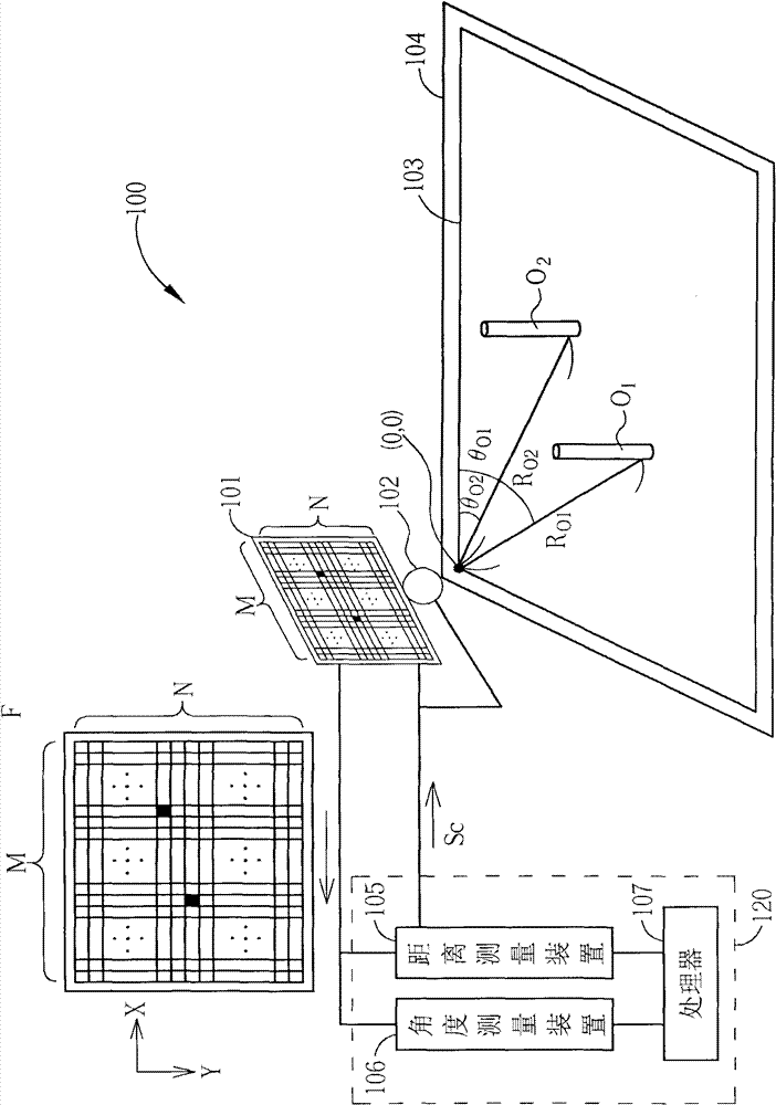
[0042] Please refer to figure 1 . figure 1 It is a schematic diagram of the optical touch screen system 100 according to the first embodiment of the present invention. The optical touch screen system 100 includes an image sensor 101 , a light emitting component 102 , a touch area 103 , a light absorbing component 104 and a processing device 120 . The processing device 120 includes a distance measuring device 105 , an angle measuring device 106 , and a processor 107 . The optical touch screen system 100 can detect multiple touch points. In addition, the distance measuring device 105 can also pass the control signal S C to control the image sensor 101 and the light emitting component 102 . At figure 1 In , only two contact points O are drawn 1 , O 2 For convenience of explanation. In addition, in figure 1 The relative position of each component in is for the convenience of description and is different from the actual setting, and the optical touch screen system 100 actu...


PUM


Abstract

The invention discloses an optical touch screen system, which comprises a light source, a reflection component, an image sensor and a processing device, wherein a light ray of the light source directly irradiates an object and irradiates a reflector to be reflected to the object and then reflected back to the image sensor; the image sensor receives the light ray which is directly reflected by the object and reflected by the reflection component, so that a static image is formed; and the processing device generates a static image parameter according to the static image and determines a coordinate of the object according to the static image parameter.

Description

technical field [0001] The invention relates to an optical touch screen system, in particular to an optical touch screen system suitable for multi-point touch. Background technique [0002] Today, touch screen technology has been widely used in various electronic products, such as automatic teller machines, handheld electronic devices, and displays. Generally speaking, touch screen technology can be divided into three types: resistive, capacitive and optical. Among them, the resistive and capacitive touch screen technologies use the electric field change on the surface of the touch screen to locate the object when the object touches the sensing device. The optical touch screen technology utilizes the blocking of the light path or the change of light and shadow when the object moves on the surface of the touch screen to locate the object. [0003] Since the optical touch screen technology does not require special processes and components in the production process of the dis...

Claims


Application Information

Patent Timeline
Patent Type & Authority Applications(China)
IPC IPC(8): G06F3/042
Inventor 吕志宏陈信嘉许恩峯廖祈杰古人豪杨恕先黄昱豪
Owner PIXART IMAGING INC
Features
  • R&D
  • Intellectual Property
  • Life Sciences
  • Materials
  • Tech Scout
  • Unparalleled Data Quality
  • Higher Quality Content
  • 60% Fewer Hallucinations
Learn More