Banknote counting machine

A banknote counting machine and frame technology, applied in the direction of counting mechanism/items, instruments, counting objects, etc., can solve the problems of short banknote transfer channel, few sensor installation positions, inconvenient upgrade and enhanced counterfeit detection functions, etc., to increase the service life , the effect of stable operation

Inactive Publication Date: 2012-10-17
上海灵岳电子设备有限公司
View PDF6 Cites 6 Cited by
  • Summary
  • Abstract
  • Description
  • Claims
  • Application Information

AI Technical Summary

Problems solved by technology

[0004] Because the banknote pulley of the banknote counter in the prior art, transmission belt pulley group, banknote output belt pulley group are driven by a drive motor, the operation of whole banknote counter is more unstable, and the motor is overloaded, and it is easy to burn for a long time; The banknote counters in the state-of-the-art are usually arranged obliquely from bottom to top. The banknote delivery channel is short and the banknote delivery space is narrow. The banknotes are driven by three transmission shafts in the banknote counter. The channel has fewer sensor installation positions, which makes the banknote checking function of the banknote counter simple, which brings inconvenience to the subsequent upgrade and enhancement of the counterfeit detection function, especially to meet the new standards of the banknote counter; During passage, since there is only one drive motor, it is difficult to drive more transmission pulley groups; in order to increase sensors in some banknote counters in the prior art, the original banknote outlet should be set at the upper end, and the original banknote outlet should be changed to the upper end. Lower-end settings, which do not conform to the user's usage habits

Method used


Image

  • Banknote counting machine
  • Banknote counting machine
  • Banknote counting machine

Examples


Embodiment Construction

[0018] The present invention will be further described below in conjunction with the accompanying drawings.

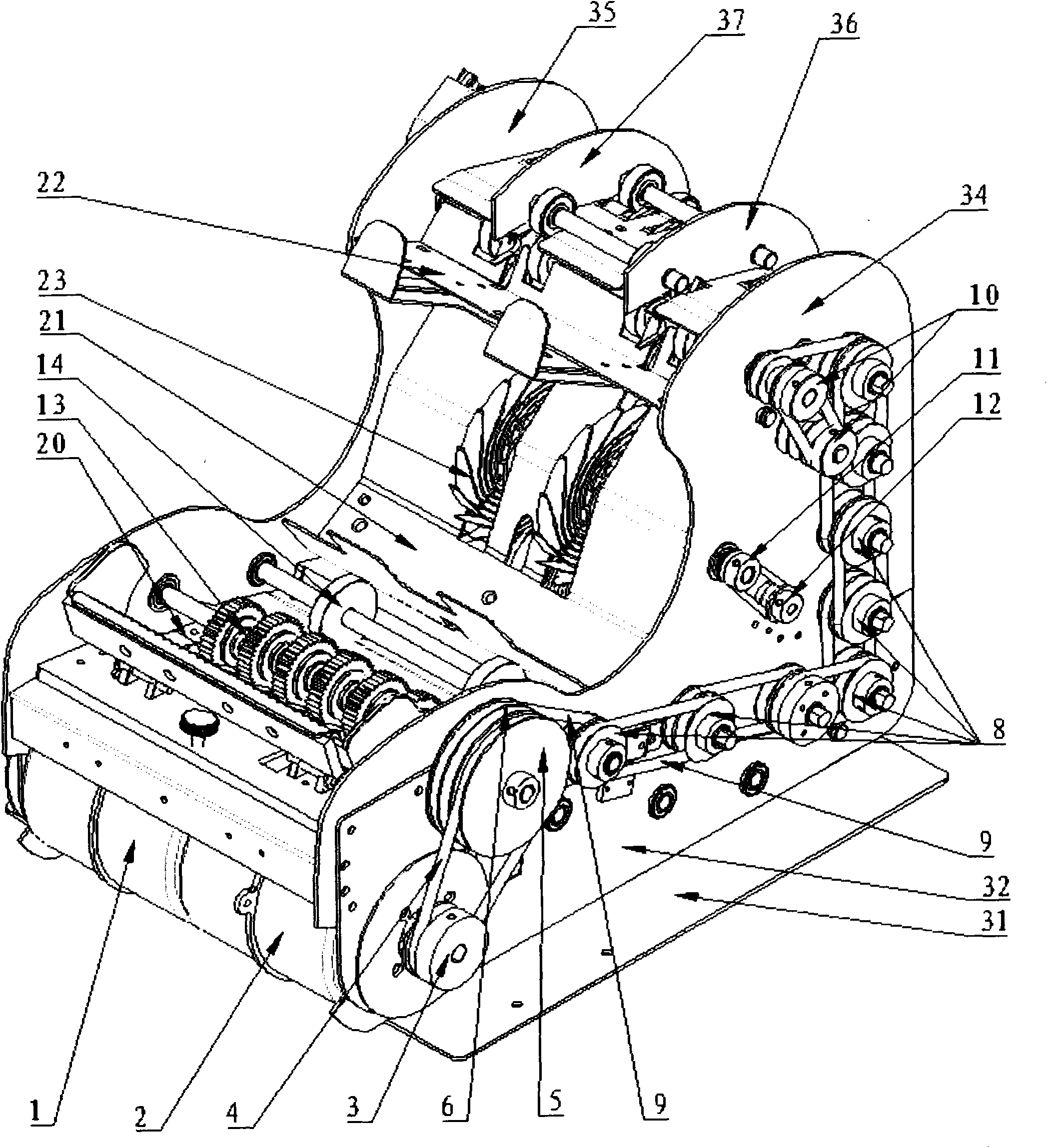
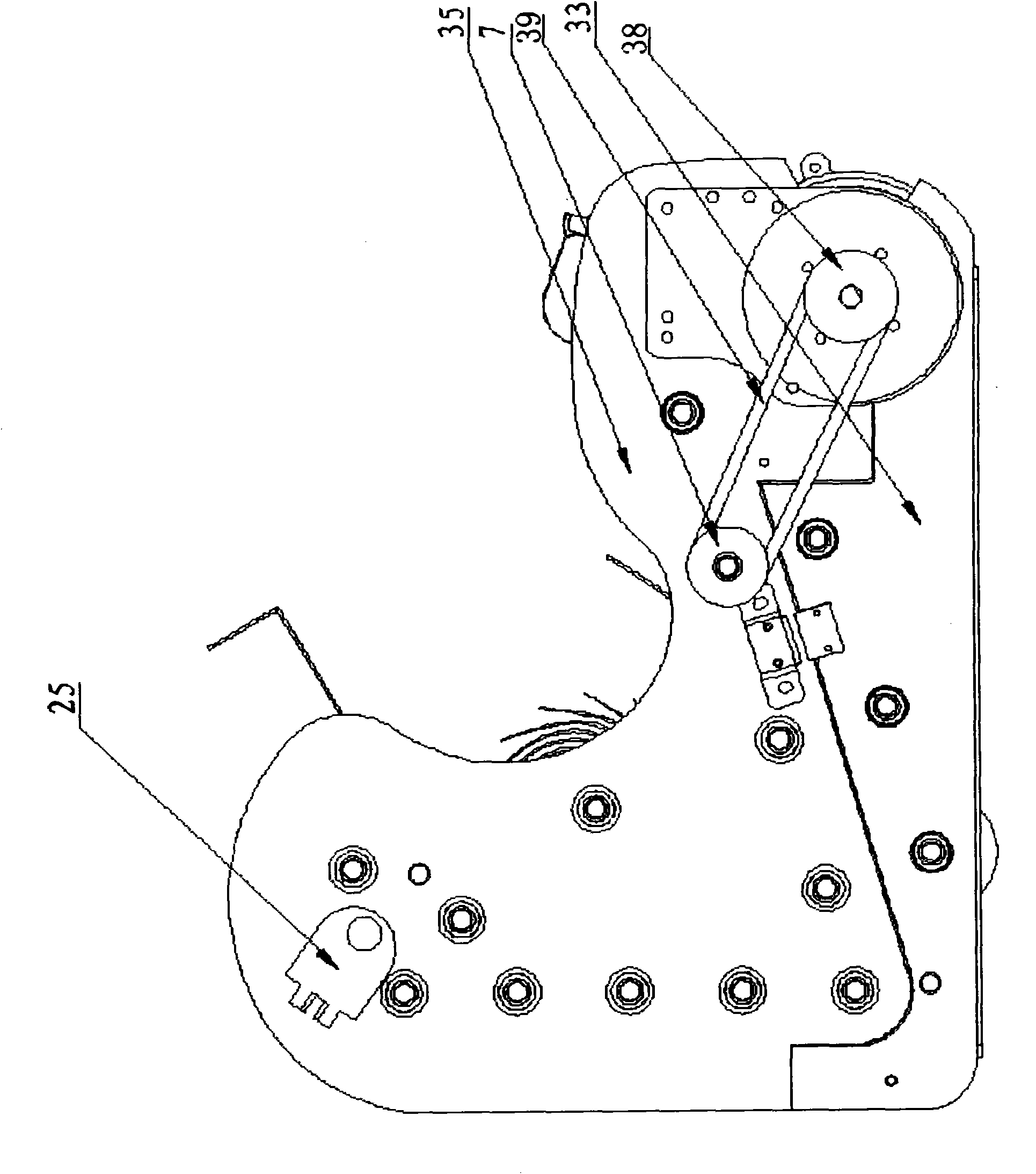
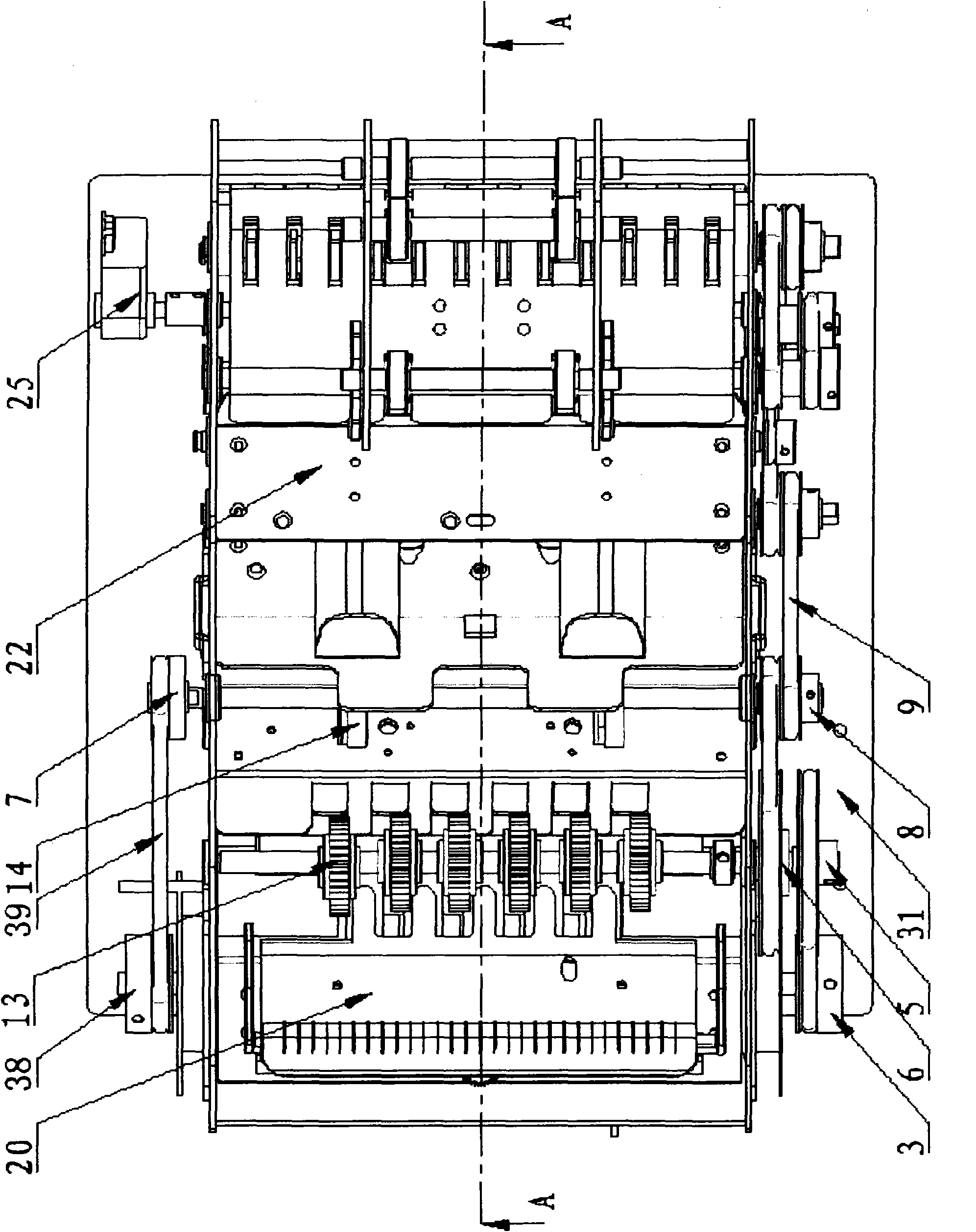
[0019] Such as figure 1 , figure 2 , image 3 Shown, a kind of banknote counter, banknote counter comprises frame, twist banknote shaft assembly 13, high-speed shaft assembly 14, the second driving motor 2, the second motor pulley 3, the second motor belt 4, and the internal transmission of the frame The transmission belt pulley group that wheel group is connected and the banknote output belt pulley group 10 that is connected with the banknote output wheel group inside the frame, the twisting banknote shaft assembly 13 and the high-speed shaft assembly 14 are all arranged on the frame, and the high-speed shaft assembly 14 is positioned at the twisting banknote shaft assembly 13 The rear side of twisting banknote shaft assembly 13 is driven by twisting banknote pulley 5, and the second driving motor 2 is arranged on the front end of frame, and the power output shaft ...


PUM


Abstract

Disclosed is a banknote counting machine. A first driving motor and a second driving motor are respectively arranged on the left side and the right side of the banknote counting machine, wherein the first driving motor is used for driving high-speed shaft components via a first motor belt pulley, a first motor belt and a single belt pulley all positioned on the left side face of a frame; the second driving motor is used for driving banknote twisting shaft components via a second motor belt pulley, a second motor belt and a banknote twisting belt pulley all positioned on the right side face of the frame; dual belt pulleys are fixedly connected to the left sides of the high-speed shaft components; the banknote twisting shaft components are provided with one-way banknote twisting belt pulleys via one-way bearings; the one-way banknote twisting belt pulleys are positioned between the right side face of the frame and the banknote twisting belt pulley; the one-way banknote twisting belt pulleys are connected with inner pulleys of the dual belt pulleys via driving belts; outer pulleys of the dual belt pulleys are connected with a driving belt pulley group via the driving belts; and the driving belt pulley group is connected with banknote output belt pulley groups via the driving belts. In the invention, owing to the two driving motors, the banknote counting machine can work more stably and has longer service life.

Description

technical field [0001] The invention relates to a money counting machine for counting the number of banknotes and identifying the authenticity of the banknotes. Background technique [0002] The banknote counter is an electromechanical integrated device that automatically counts the number of banknotes and identifies counterfeit currency. Banknote counters are usually set up in offices with a large amount of cash circulation, and banknote counters have become indispensable equipment. [0003] The banknote counter of prior art comprises frame, twist banknote shaft assembly, high-speed shaft assembly, drive motor, motor belt pulley, motor belt, the transmission belt pulley group that is connected with frame internal transmission wheel group and the banknote output wheel group that is connected with frame interior. The connected banknote output belt pulley group, the twisting banknote shaft assembly and the high-speed shaft assembly are all arranged on the frame, the high-spee...

Claims


Application Information

Patent Timeline
Patent Type & Authority Applications(China)
IPC IPC(8): G07D13/00G06M7/06
Inventor 林天祥
Owner 上海灵岳电子设备有限公司
Why Eureka
Try Eureka