Energy-saving constant-temperature power distribution cabinet

A power distribution cabinet and constant temperature technology, which is applied in the substation/power distribution device shell, energy industry, electrical components, etc., can solve the hidden dangers of equipment safe operation, outdoor sites are easily affected by environmental temperature changes, and increase production costs. Ensure normal and safe operation, not easy to break down or even burn out, and prolong the service life

Inactive Publication Date: 2015-04-29
STATE GRID CORP OF CHINA +2
View PDF4 Cites 4 Cited by
  • Summary
  • Abstract
  • Description
  • Claims
  • Application Information

AI Technical Summary

Problems solved by technology

[0002] Existing large-scale power main equipment needs to realize on-site data collection and control, thus causing a large number of measurement and protection devices originally installed in the control room to be moved to the outdoor equipment site, compared with the constant temperature and humidity environment of the control room , outdoor venues are easily affected by changes in ambient temperature, hot in summer and cold in winter, and are extremely susceptible to moisture, which brings serious hidden dangers to the safe operation of equipment
Due to the needs of smart grid construction, the above-mentioned new problems have arisen. Conventional electric cabinets lack the means to adjust temperature and humidity, which cannot be solved. Some smart grid equipment manufacturers use ventilation

Method used


Image

  • Energy-saving constant-temperature power distribution cabinet
  • Energy-saving constant-temperature power distribution cabinet

Examples


Example Embodiment

[0013] The technical solution of this patent will be described in further detail below in conjunction with specific embodiments.
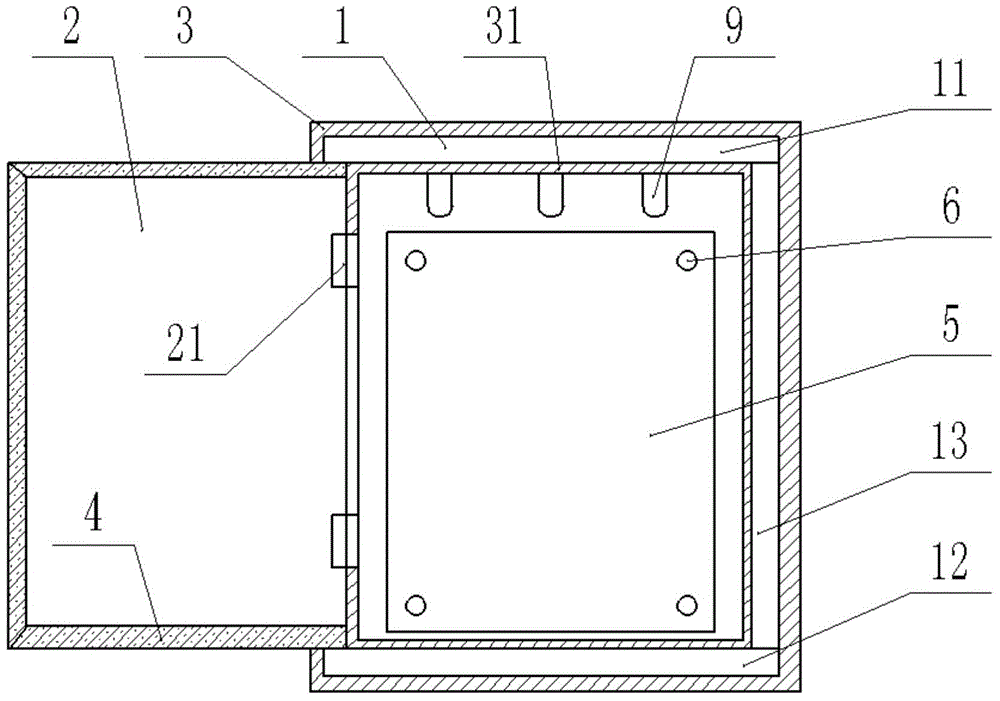
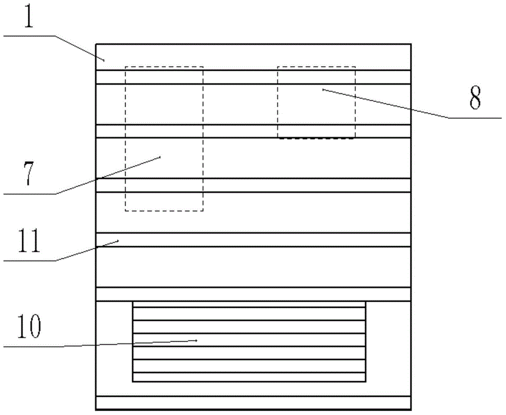
[0014] See Figure 1-2 , An energy-saving constant temperature power distribution cabinet, comprising a cabinet body 1 and an industrial air conditioner 10. The cabinet body 1 is composed of a top plate 101, a bottom plate 102 and a side plate 103. The cabinet body 1 is provided with a cabinet door 2, and the cabinet door 2 is hinged 21 is connected to the cabinet 1, the cabinet 1 and the cabinet door 2 are covered with an insulation layer 3. The thickness of the insulation layer 3 is 1-5 cm, which can effectively block the heat generated by the electrical equipment in the electrical cabinet. 1 and the cabinet door 2 are provided with a flocking layer 31 on the inner wall to prevent air and water from condensing in the cabinet 1 to form water droplets. A gasket 4 is provided where the cabinet door 2 and the cabinet 1 are attached, and the gasket 4 is ...


PUM


Abstract

The invention discloses an energy-saving constant-temperature power distribution cabinet. The cabinet comprises a cabinet body and an industrial air conditioner, wherein the cabinet body consists of a top plate, a bottom plate and side plates, a cabinet door is arranged on the cabinet body and connected onto the cabinet body through hinges, outer sides of the cabinet body and the cabinet door are coated with heat-insulation layers, flocked layers are arranged on inner walls of the cabinet body and the cabinet door, and a sealing gasket is arranged in a position where the cabinet door and the cabinet body are attached to each other and is formed by splicing multiple sections of silica gel adopting rectangular structures; a drain type power distribution cabinet dehumidifier, a digital temperature and humidity monitor and LED lamps are arranged in the cabinet body, and the industrial air conditioner is arranged behind an outer case of the cabinet body. The cabinet cannot break down and even be burnt down easily, is high in safety performance and simple in structure and is not required to be replaced frequently, the production cost is reduced, structures of existing power distribution cabinets are changed, defects of the existing power distribution cabinets are overcome, and normal and safe operation of electrical equipment in the power distribution cabinet is guaranteed.

Description

technical field [0001] The invention relates to a power distribution cabinet, in particular to an energy-saving constant temperature power distribution cabinet. Background technique [0002] Existing large-scale power main equipment needs to realize on-site data collection and control, thus causing a large number of measurement and protection devices originally installed in the control room to be moved to the outdoor equipment site, compared with the constant temperature and humidity environment of the control room , Outdoor venues are easily affected by changes in ambient temperature. It is hot in summer and cold in winter, and is extremely prone to moisture, which brings serious hidden dangers to the safe operation of equipment. Due to the needs of smart grid construction, the above-mentioned new problems have arisen. Conventional electric cabinets lack the means to adjust temperature and humidity, which cannot be solved. Some smart grid equipment manufacturers use ventila...

Claims


Application Information

Patent Timeline
IPC IPC(8): H02B1/28H02B1/56H02J13/00
CPCH02B1/24H02B1/28H02B1/565Y02B70/30Y02P80/10Y04S20/244
Inventor 许浩李念淼陈颖朱晞旸王海军卢轶人
Owner STATE GRID CORP OF CHINA
Why Eureka
Try Eureka