
Communication method and communication system

A communication method and communication system technology, applied in the field of communication methods and communication systems, can solve problems such as long service interruption time, and achieve the effect of reducing service interruption time

Active Publication Date: 2012-10-17
HUAWEI TECH CO LTD
View PDF5 Cites 4 Cited by
  • Summary
  • Abstract
  • Description
  • Claims
  • Application Information

AI Technical Summary

Problems solved by technology

[0004] In the prior art, re-ranging will cause service interruption for a long time

Method used


Image

  • Communication method and communication system
  • Communication method and communication system
  • Communication method and communication system

Examples


Embodiment Construction

[0017] The following will clearly and completely describe the technical solutions in the embodiments of the present invention with reference to the accompanying drawings in the embodiments of the present invention. Obviously, the described embodiments are only some, not all, embodiments of the present invention. Based on the embodiments of the present invention, all other embodiments obtained by persons of ordinary skill in the art without creative efforts fall within the protection scope of the present invention.

[0018] Embodiments of the present invention provide a communication method and a communication system. Detailed descriptions are given below

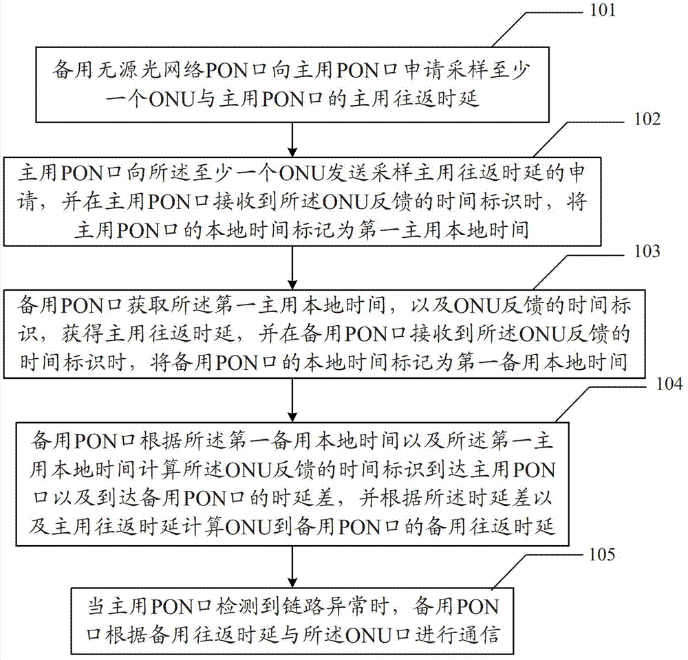
[0019] see figure 1 , the first embodiment of the communication method in the embodiment of the present invention includes:

[0020] 101. The standby passive optical network PON port applies to the active PON port for sampling the main round-trip delay between at least one optical network unit ONU and the active PON port; ...


PUM


Abstract

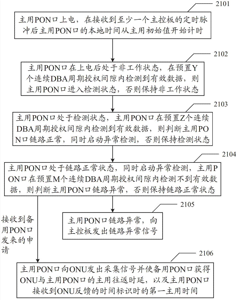
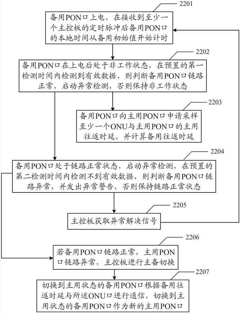
The embodiment of the invention discloses a communication method and a communication system which are applied in the technical field of communication. The communication method comprises the following steps that: a main passive optical network (PON) port sends a sampling main round-trip delay request to at least one optical network unit (ONU), and the local time of the main PON port is marked as a first main local time when a time mark fed back by the ONU is received; a standby PON port acquires the first main local time and the time mark fed back by the ONU to acquire a main round-trip delay, and the local time of the standby PON port is marked as a first standby local time when the time mark is acquired; the standby PON port calculates delay differences according to the first standby local time and the first main local time, and calculates the standby round-trip delay according to the delay differences and the main round-trip delay; and when the main PON port detects that a link is abnormal, the standby PON port communicates with the ONU according to the standby round-trip delay. The communication method and the communication system can ensure that the service interruption time is significantly reduced.

Description

technical field [0001] The present invention relates to the technical field of communication, in particular to a communication method and a communication system. Background technique [0002] Ethernet Passive Optical Networks (EPON, Ethernet Passive Optical Networks) is a single-fiber bidirectional optical access network using a point-to-multipoint structure, and its typical topology is a tree. The Ethernet passive optical network system consists of an optical line terminal (OLT, Optical Line Terminal) at the office side, an optical network unit (ONU, Optical Network Unit) at the user side, and an optical distribution network (ODN, Optical Distribution Network). ODN is composed of optical fiber and one or more passive optical components such as passive optical splitters, and provides optical channels between OLT and ONU. In the downlink direction, the signal sent by the OLT reaches each ONU through the ODN. In the uplink direction, a Time Division Multiple Access (TDMA, Ti...

Claims


Application Information

Patent Timeline
IPC IPC(8): H04Q11/00
Inventor 李南于田昌李瑞彬
Owner HUAWEI TECH CO LTD
Learn More