Luminaire assembly

A technology for lighting devices and headlights, applied in signal devices, lighting and heating equipment, transportation and packaging, etc., can solve the problems of short service life, large structure, multi-energy, etc., and achieve extended service life and high service life , the effect of saving energy

Inactive Publication Date: 2012-10-17
OSRAM GMBH
View PDF8 Cites 0 Cited by
  • Summary
  • Abstract
  • Description
  • Claims
  • Application Information

AI Technical Summary

Problems solved by technology

Higher luminous fluxes can be achieved, for example, by more efficient halogen lamps, but these are more complex in terms of equipment and require more energy than lower-efficiency halogen lamps
Alternatively, conventional halogen lamps with increased efficiency can also be used, which disadvantageously leads to a shorter service life

Method used


Image

  • Luminaire assembly

Examples


Embodiment Construction

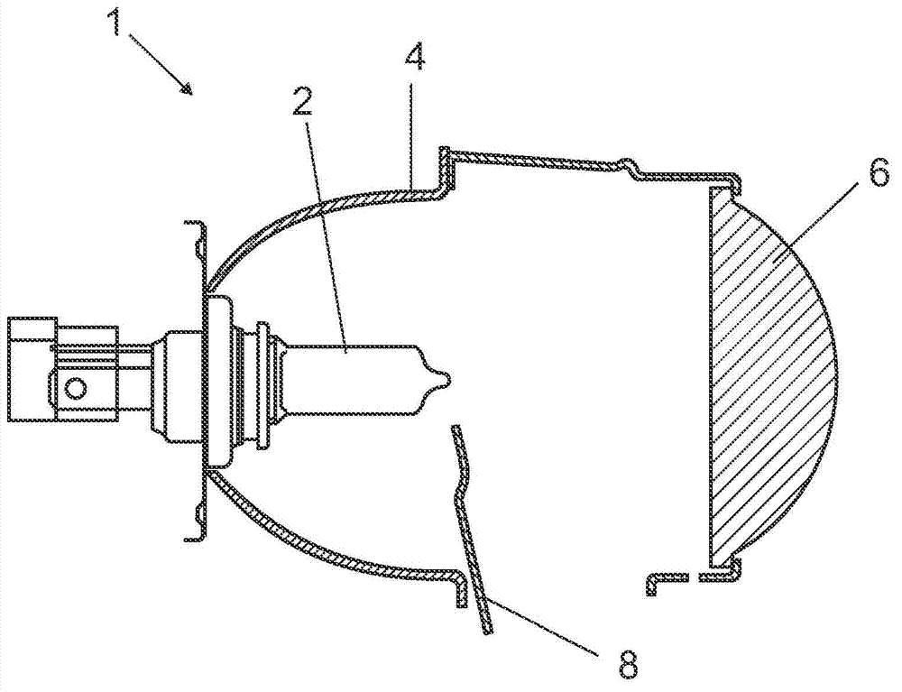
[0019] The single figure shows a very simplified schematic illustration of a lighting device 1 according to an exemplary embodiment. In this case it is a double halogen headlight for motor vehicles. These headlamps produce low and high beams from a single light source. In the shown figures, in this case an H7 halogen incandescent lamp, which is referred to below as lamp 2 . The H7 halogen incandescent lamp has only one filament coil, which is used as a light source for generating the high beam and also as a light source for generating the low beam.

[0020] The lighting device 1 has a reflector 4 surrounding the lamp 2 and a projection lens 6 in the beam path.

[0021] Via a shutter 8 arranged between the projection lens 6 and the lamp 2 , it is possible to switch between the low-beam lighting function and the high-beam lighting function. The low-beam lighting function and the high-beam lighting function therefore differ in that the cross-section of the beam path is larger ...


PUM


Abstract

The invention relates to a luminaire assembly (1), in particular a bi-halogen headlight for a motor vehicle, comprising a light source (2) having at least two lighting functions. The operating voltages of the light source (2) for an associated lighting function differ relative to each other.

Description

technical field [0001] The invention relates to a lighting device according to the preamble of claim 1 . Background technique [0002] Document DE 10 2006 057 748 A1 discloses such a lighting device for a vehicle headlight. In this case, a double-halogen headlight, by means of which the low beam and the high beam are generated from a single light source. When the high beams of the vehicle are activated, the visor is magnetically moved out of the light path of the light source in order to free up a larger area of ​​the light path. Conversely, when switching from high beam to low beam, the visor is moved into the beam path. When switching between high beam and low beam, the light color and light intensity remain basically the same. For such dual halogen headlamps, for example, H7 halogen lamps or H9 halogen lamps are used as light sources. Alternatively, a xenon lamp can be used as light source. [0003] Vehicle headlights of this type have a significantly higher shading ...

Claims


Application Information

Patent Timeline
Patent Type & Authority Applications(China)
IPC IPC(8): B60Q1/14
CPCB60Q1/1415F21S41/00B60Q1/08B60Q1/1438
Inventor 哈拉尔德·卡普斯克劳斯·维特曼奥利弗·赫林彼得·黑尔比希
Owner OSRAM GMBH
Why Eureka
Try Eureka