Movement device with decoupled position regulators

A technology for azimuth regulators and motion devices, applied to magnetic attraction or thrust holding devices, measuring devices, control devices, etc., can solve problems such as high energy and loss

Pending Publication Date: 2019-12-20
ROBERT BOSCH GMBH
View PDF2 Cites 0 Cited by
  • Summary
  • Abstract
  • Description
  • Claims
  • Application Information

AI Technical Summary

Problems solved by technology

This results in high energy loss

Method used


Image

  • Movement device with decoupled position regulators
  • Movement device with decoupled position regulators
  • Movement device with decoupled position regulators

Examples


Embodiment Construction

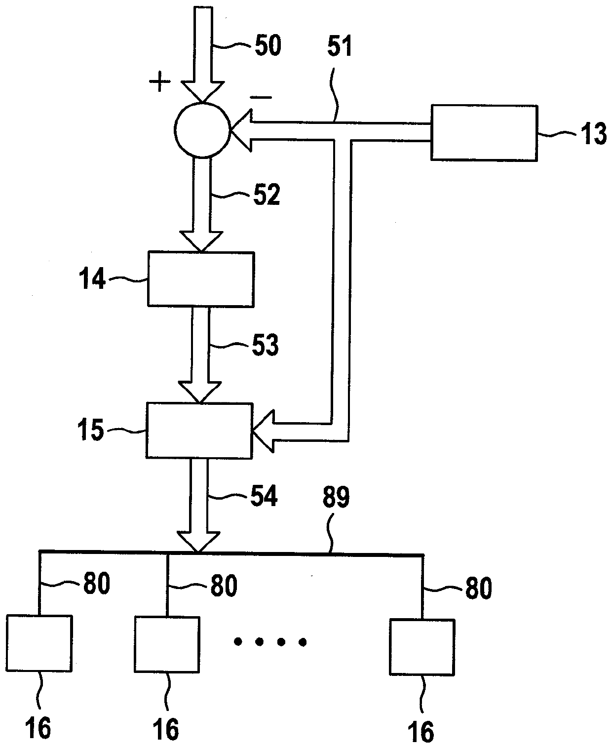
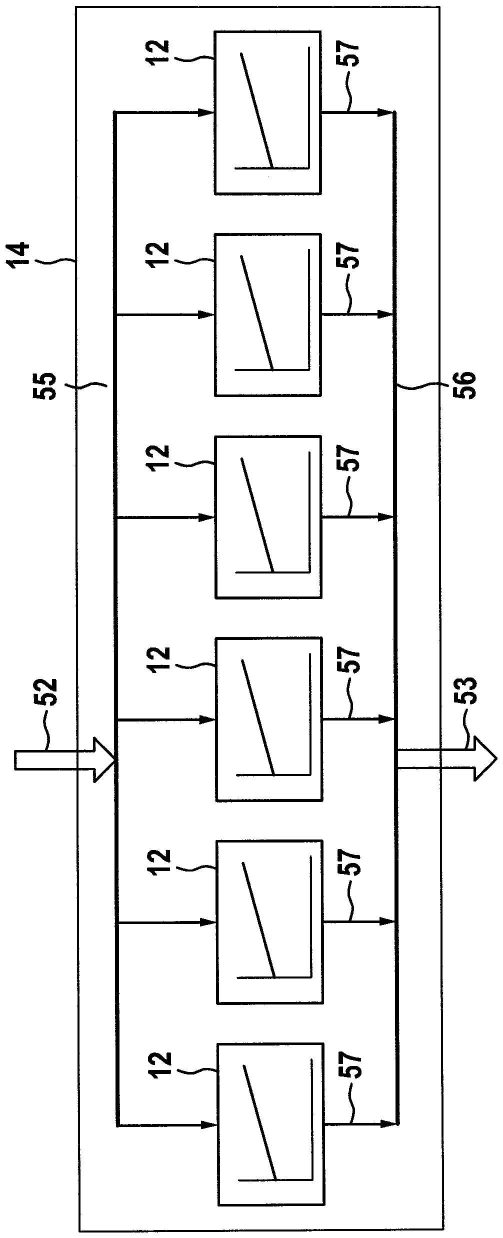
[0035] figure 1 A roughly schematic sectional view of the sports device 10 according to the invention is shown. The movement device 10 here comprises a single first component 20 and a single second component 30 , the first component being in the form of a stationary stator, the second component being in the form of a movable workpiece carrier . The stator is typically designed with respect to its movement surface 25 to be much larger than the workpiece carrier. The assignment of the first and second components to the stator and the workpiece carrier can also be selected inversely. Components different from the stator can exist multiple times.

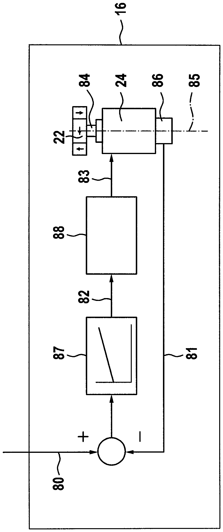
[0036] The first component 20 includes a base 21 , which is here designed in the manner of a completely closed housing. Here, the upper side of the base 21 forms a closed planar movement surface 25 along which the second component 30 can move freely suspended. In this case, the movement surface 25 is oriented perpendicular to the d...


PUM


Abstract

The disclosure relates to a method for operating a movement apparatus having a first assembly and a second assembly. The first assembly includes a base and several permanent-magnet arrangements that are connected to the base via actuators such that they move as a whole relative to the base in at least one degree of freedom by the assigned actuator, the second assembly including a base and a permanent-magnet arrangement arranged firmly relative to the base. Position controllers are provided, each with a controlled variable and with a correcting variable. The controlled variable is one of six possible degrees of freedom with regard to a relative position between the first and second assembly. The correcting variable represents a force or a torque that has been assigned to the degree of freedom. Desired positions of the actuators are computed from the correcting variables and/or by means of a number table, and the actuators are set accordingly.

Description

technical field [0001] The invention relates to a method for operating a sports device according to claim 1 and a sports device according to claim 11 which is designed according to this method. With such a movement device, the second component can be held in suspension relative to the first component and moved in a controlled manner solely by magnetic force, the roles of the first and second component being able to be reversed as well. Background technique [0002] A movement device is known from WO 2015 / 017 933 A1 in which a magnetic force is generated by means of electromagnets. This results in high energy losses. [0003] In the German patent application with file number 102016224951.7, the applicant describes a completely novel movement device with which the functions known from WO 2015 / 017 933 A1 can be implemented solely through the use of permanent magnets. As a result, much less waste heat is produced, while at the same time much greater loads can be kept in suspen...

Claims


Application Information

Patent Timeline
Patent Type & Authority Applications(China)
IPC IPC(8): G05D3/12B60L13/10G01B7/004G05B19/402
CPCG05D3/12B60L13/10G01B7/004G05B19/402B60L13/08B60L2240/423B60L2260/48B60L2240/32G01D5/2086Y02T10/64G01D5/2073H02N15/00H01F7/0236
Inventor J.弗兰根
Owner ROBERT BOSCH GMBH
Why Eureka
Try Eureka