Turbo engine with power turbine

A technology of turbine engine and power turbine, applied in engine components, combustion engine, engine lubrication, etc., can solve problems such as unreliable transmission mechanism

Inactive Publication Date: 2012-12-05
MAN B & W DIESEL AS
View PDF0 Cites 0 Cited by
  • Summary
  • Abstract
  • Description
  • Claims
  • Application Information

AI Technical Summary

Problems solved by technology

But here the very high rotational speed difference between the power turbine and the engine shaft needs to be overcome, so that this configuration is not reliable due to the large transmission required

Method used


Image

  • Turbo engine with power turbine
  • Turbo engine with power turbine

Examples


Embodiment Construction

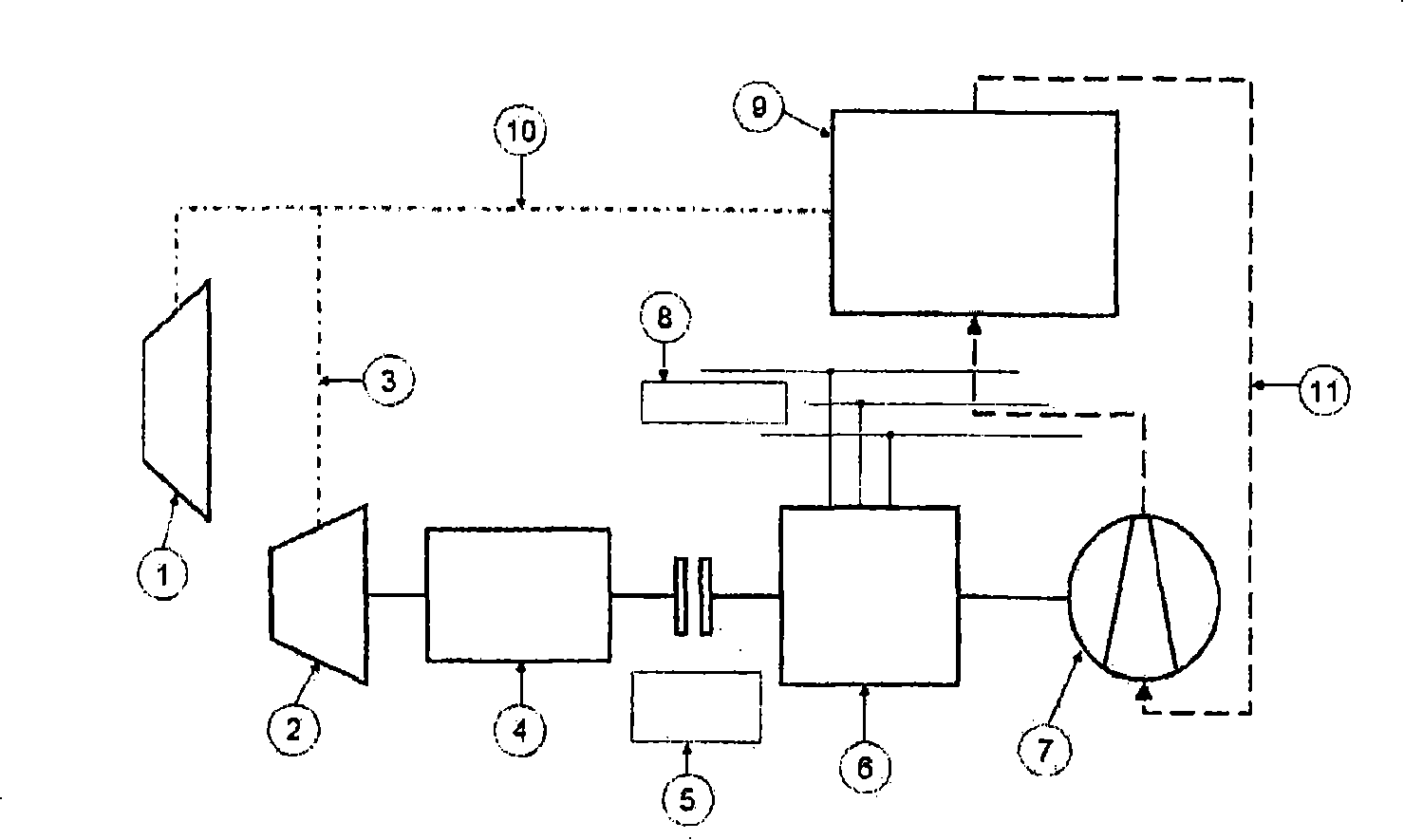
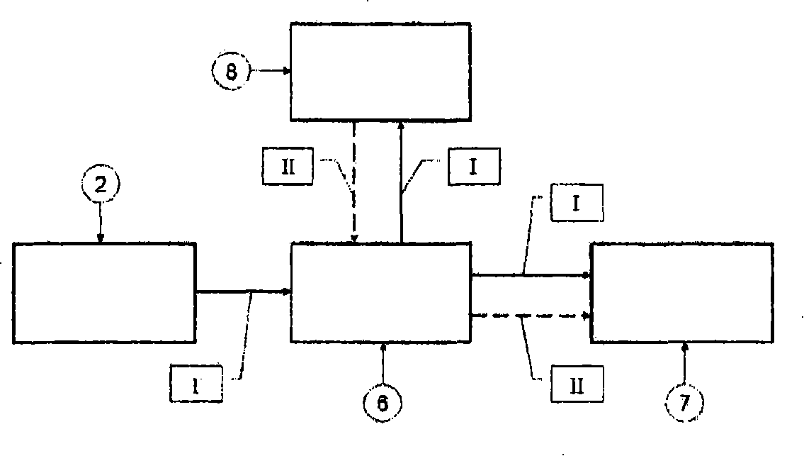
[0028] figure 1 Shown is a turbocharger 1 arranged in an exhaust gas line 10 of an internal combustion engine 9 , which serves to increase the specific power of the internal combustion engine 9 by supercharging. The power turbine 2 is arranged in the exhaust gas branch line 3 and is driven by exhaust gas energy which has not been utilized so far. The rotational movement of the power turbine 2 is transmitted to the actuating clutch 5 via a suitable transmission 4 via a mechanical connection.

[0029] On the other side, the actuating clutch 5 is mechanically coupled to the electric machine 6 . When the actuating clutch 5 is in the operating position, a mechanical force transmission from the actuating clutch 5 to the electric machine 6 takes place. In addition, the electric machine 6 is still connected to the ship's power grid, which is run trouble-free, for example by means of several standby generator sets, and which can deliver a constant-frequency current to the electric ma...


PUM


Abstract

The turbocharged engine, particularly large diesel engine, has a turbocharger stage (1) and a utility turbine (2) for using an excess exhaust gas mass flow (3). An oil pump assembly (7) and an electrical machine (6) is mechanically coupled with the utility turbine by a gear box (4) and connected electrically with a power supply (8). The oil pump assembly is mechanically coupled to the electrical machine and a decoupling device (5) is provided for mechanically decoupling the utility turbine and the electrical machine.

Description

technical field [0001] The invention relates to a turbine engine, especially a large diesel engine. Background technique [0002] A large diesel engine is typically a large diesel engine used as a main engine or an auxiliary engine, for example on a ship. In practice, identical engines are used stationary in power stations, especially in other remote locations, and also as emergency power plants, for example in hospitals, large banks, computing centers and nuclear power plants. [0003] Large diesel engines can work on diesel, gas oil or heavy oil. The name refers to a working process which by definition is characterized by the intake of air and spontaneous combustion after injection of fuel. [0004] Two-stroke engines are mostly constructed as in-line machines, while four-stroke engines are mainly constructed in an in-line arrangement and as a V-engine arrangement. Larger marine diesel engines are generally two-stroke engines, which are designed as in-line engines with ...

Claims


Application Information

Patent Timeline
Patent Type & Authority Patents(China)
IPC IPC(8): F02B41/10F01M1/02
CPCF01M2001/0253F02G5/02Y02T10/166Y02T10/163F01N5/04Y02T10/16F01M1/02F02B41/10Y02T10/12F02B37/14F02B39/02F02B39/12F02B39/14
Inventor F·沃德克
Owner MAN B & W DIESEL AS
Why Eureka
Try Eureka