Rotary conduction mechanism

A technology of a rotating device and a conductive device, applied in the electrolysis process, electrolysis components, etc., can solve the problems of long replacement time, low efficiency, high labor intensity of workers, etc., and achieve the effect of uniform surface coating

Inactive Publication Date: 2012-10-24
WUXI PENTE ENVIRONMENTAL PROTECTION ENG
View PDF6 Cites 0 Cited by
  • Summary
  • Abstract
  • Description
  • Claims
  • Application Information

AI Technical Summary

Problems solved by technology

[0002] When electroplating the mandrel, the old-fashioned conductive mechanism used the terminal to conduct electricity. When replacing the mandrel, the conductive head needs to be disassembled and then installed on the new mandrel for electroplating. The labor intensity of the workers is high and the efficiency is low. Replacement It takes a long time, and new devices are needed to solve the above problems

Method used


Image

  • Rotary conduction mechanism
  • Rotary conduction mechanism

Examples


Embodiment Construction

[0024] The preferred embodiments of the present invention will be described below in conjunction with the accompanying drawings. It should be understood that the preferred embodiments described here are only used to illustrate and explain the present invention, and are not intended to limit the present invention.

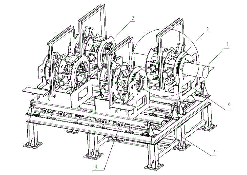
[0025] Such as figure 1 , 2 As shown, the rotating conductive mechanism includes a rotating device 2 , a conductive device 3 and a transmission device 4 .

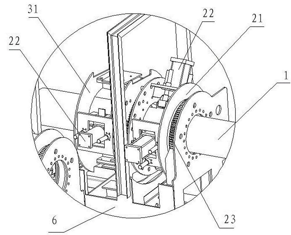
[0026] The rotating device 2 mainly includes a rotating supporting piece 21 , a servo motor, a gear 23 and a pressing cylinder 22 .

[0027] There is a central hole in the center of the rotating support piece for the workpiece 1 to pass through, and there are installation holes evenly distributed along the circumference around the center hole for installing the compression cylinder. The two rotating supporting pieces are placed in parallel and the axes of the central holes are horizontal. A compression cylinde...


PUM


Abstract

The invention provides a rotary conduction mechanism. The rotary conduction mechanism comprises a rotating device, a conducting device and a conveying device, wherein the rotating device consists of a servo motor, a compaction cylinder and the like, and the servo motor can regulate the rotation speed of a mechanism according to the self-rotation speed of a mandril during traveling. The conducting device is used for conducting by utilizing a carbon brush, and a spring steel sheet is arranged at the tail part of the carbon brush so as to automatically regulate the abrasion loss; and the whole conducting device is compacted on the mandril through the compaction cylinder and is connected with the rotating device through a rotary support to synchronously work. A conveying device is used for conveying the rotating device and the conducting device forwards, and the conveying motor of the conveying device is a variable frequency motor and can freely set the conveying speed. According to the rotary conduction mechanism, the rotating device, the conducting device and the conveying device work together so as to reach a purpose of rotary electricity conduction, a follow-up patch type electricity conduction operation is realized, and the rotary electricity conduction of the mandril can be realized in an electroplating process, thus the surface plating layer is more uniform.

Description

technical field [0001] The invention relates to a conductive mechanism and belongs to the field of electroplating conductive devices. Background technique [0002] When electroplating the mandrel, the old-fashioned conductive mechanism used the terminal to conduct electricity. When replacing the mandrel, the conductive head needs to be disassembled and then installed on the new mandrel for electroplating. The labor intensity of the workers is high and the efficiency is low. Replacement The time is long, need novel device to solve the above problems. Contents of the invention [0003] The technical problem to be solved by the present invention is to overcome existing defects and provide a rotating conductive mechanism, which can enable continuous electroplating without dismantling the conductive head during mandrel electroplating. [0004] In order to solve the problems of the technologies described above, the present invention provides the following technical solutions: ...

Claims


Application Information

Patent Timeline
Patent Type & Authority Applications(China)
IPC IPC(8): C25D17/00
Inventor 钱迎清
Owner WUXI PENTE ENVIRONMENTAL PROTECTION ENG
Why Eureka
Try Eureka