
Floating caliper disc center brake with automatic return mechanism

An automatic return and brake technology, which is applied in the direction of brake actuators, gear transmission mechanisms, mechanical equipment, etc., can solve the problem of increasing parking brake clearance, parking brake failure, inability to overcome mechanical friction and torque, etc. problems, to achieve the effect of eliminating partial wear and dragging

Active Publication Date: 2015-04-08
DONGFENG OFF ROAD VEHICLE CO LTD
View PDF4 Cites 0 Cited by
  • Summary
  • Abstract
  • Description
  • Claims
  • Application Information

AI Technical Summary

Problems solved by technology

At present, the parking brake failure problem of the central floating caliper disc central brake of off-road vehicles is prominent due to the dragging of the rear brake shoe. How to improve the mean distance between failures of the parking brake is an important issue in the industry.
The original parking brake comes with a return spring for the friction plate. After the parking brake is released, the rear friction plate cannot overcome the mechanical friction and torque between the caliper body and the sliding pin, resulting in the rear friction plate clinging to the parking brake. The phenomenon of brake dragging occurs on the disc. The dragging directly causes the premature wear of the rear friction plate and increases the parking brake clearance. When the clearance increases beyond the automatic parking clearance adjustment range, the parking brake fails.
The average mileage between failures of existing brakes is 500Km, and the reliability is poor

Method used


Image

  • Floating caliper disc center brake with automatic return mechanism

Examples


Embodiment Construction

[0011] The present invention will be further described below in conjunction with the accompanying drawings and examples.

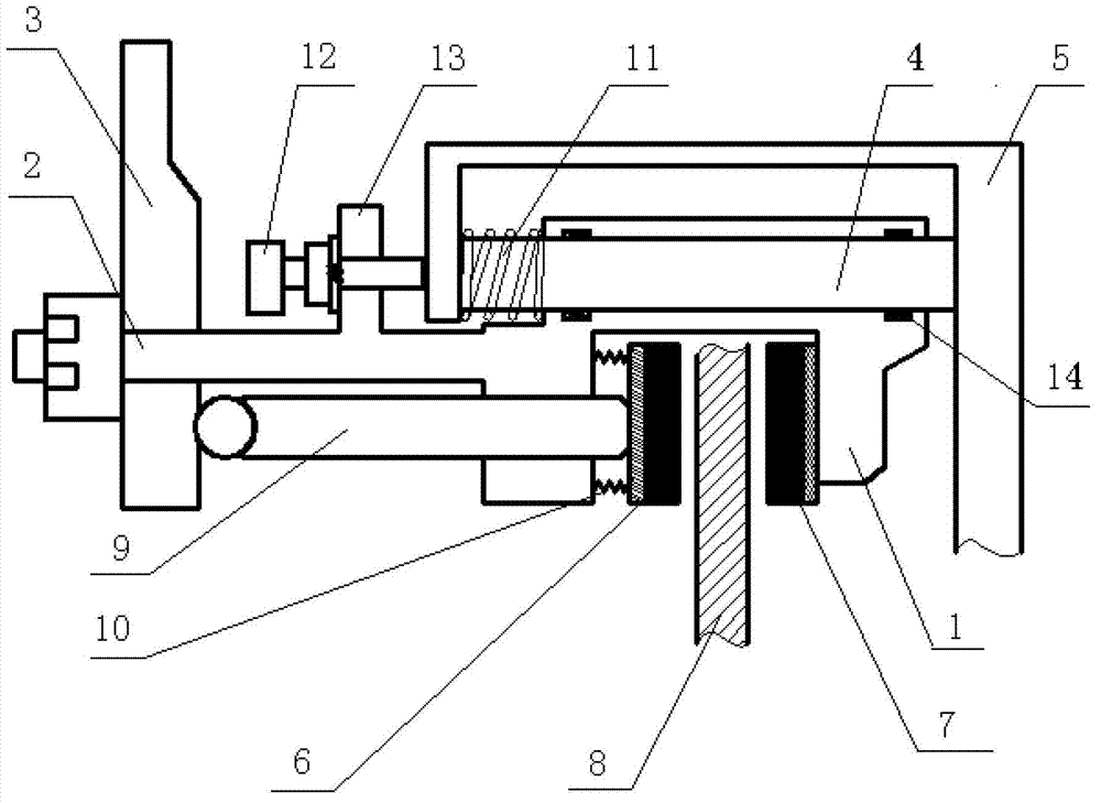
[0012] figure 1 It is a structural schematic diagram of the present invention: the floating caliper disc central brake with an automatic return mechanism of the present invention includes a central brake caliper body 1, a rocker shaft 2 and a rocker arm 3 connected to the central brake caliper body 1, passing through the central brake The sliding pin 4 of the caliper body 1, the sliding pin bracket 5, the front brake shoe 6 and the rear brake shoe 7 installed on the central brake caliper body 1, are located at the front brake shoe 6 and the rear brake shoe 7 Between the central brake disc 8, the brake ejector pin assembly 9, the front friction block return spring 10, and the sliding pin 4 between the rear end of the central brake caliper body 1 and the sliding pin bracket 5 is covered with a compression spring 11. A limit plate 13 protrudes from the centr...


PUM


Abstract

The invention provides a floating caliper disc center brake with an automatic return mechanism, which comprises a center brake caliper body, a rocker arm shaft, a rocker arm, a sliding pin, a sliding pin bracket, a front brake shoe, a rear brake shoe, a center brake disc, a brake lifting pin assembly and a front friction block return spring, wherein the rocker arm shaft and the rocker arm are connected with the center brake caliper body; the sliding pin passes through the center brake caliper body; the front brake shoe and the rear brake shoe are arranged on the center brake caliper body; the center brake disc is positioned between the front brake shoe and the rear brake shoe; a compression spring is sleeved on the sliding pin between the rear end of the center brake caliper body and the sliding pin bracket; a limit plate extends out of the center brake caliper body; a gap adjustable stop screw is arranged on the limit plate; the rod end of the gap adjustable stop screw corresponds to the sliding pin bracket at the position of the compression spring; rectangular sealing rings are arranged at both ends of the sliding pin in the center brake caliper body; in an initial state, the gap adjustable stop screw is attached to the sliding pin bracket; and the gap adjustable stop screw and the sliding pin are coaxially arranged.

Description

technical field [0001] The invention relates to the technical field of automobile brakes, in particular to a floating caliper disc-type central brake with an automatic return mechanism. Background technique [0002] With the diversification of modern off-road vehicle equipment, the self-weight of the vehicle itself continues to increase, the safety requirements continue to increase, and the braking performance requirements of the vehicle are also getting higher and higher. At present, the failure of the parking brake caused by the dragging of the rear brake shoe of the central floating caliper disc central brake of off-road vehicles is prominent. How to improve the mean distance between failures of the parking brake is an important issue in the industry. The original parking brake comes with a return spring for the friction plate. After the parking brake is released, the rear friction plate cannot overcome the mechanical friction and torque between the caliper body and the s...

Claims


Application Information

Patent Timeline
Patent Type & Authority Patents(China)
IPC IPC(8): F16D65/22F16D65/48F16D121/14
Inventor 范仲周旺生王法春王聪
Owner DONGFENG OFF ROAD VEHICLE CO LTD
Learn More