Linear compressor-driven travelling wave loop pulse tube refrigerator

A pulse tube refrigerator, linear compressor technology, applied in refrigerators, compressors, refrigeration and liquefaction and other directions, can solve the problems affecting the compactness of the pulse tube refrigerator, unfavorable applications, etc., to achieve compact structure and small pressure fluctuations. , the effect of suppressing DC flow

Inactive Publication Date: 2012-10-24
TECHNICAL INST OF PHYSICS & CHEMISTRY - CHINESE ACAD OF SCI
View PDF4 Cites 11 Cited by
  • Summary
  • Abstract
  • Description
  • Claims
  • Application Information

AI Technical Summary

Problems solved by technology

Except for the gas storage, the volume of each component of the cold finger is small compared to the compressor, but the volume of the gas storage is basically the same as that

Method used


Image

  • Linear compressor-driven travelling wave loop pulse tube refrigerator
  • Linear compressor-driven travelling wave loop pulse tube refrigerator
  • Linear compressor-driven travelling wave loop pulse tube refrigerator

Examples


Embodiment 1

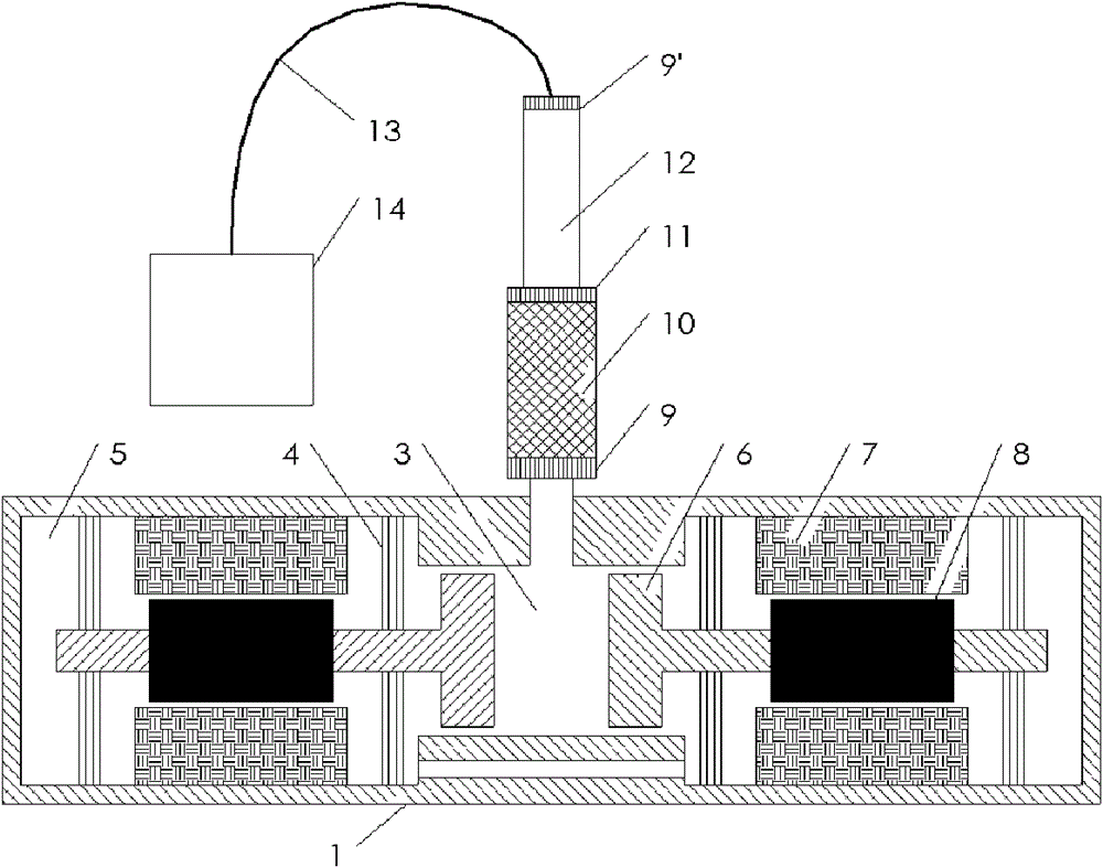
[0021] figure 2 Shown is a schematic structural diagram of Embodiment 1 of the present invention.

[0022] In the traveling-wave circuit pulse tube refrigerator driven by a linear compressor in this embodiment, the linear compressor is a double linear compressor structure opposite to the left and right, and the stator 7 is fixed together with the shell of the linear compressor, which is a non-moving part. The outer circle of the spring 4 is fixed with the compressor casing, and the inner circle of the compressor supports the mover 8 and the piston 6, and the mover 8 reciprocates with the piston 6 through the electromagnetic force between the stator 7 and generates pressure waves. And the cold finger is input through the front cavity 3 of the compressor; the structure of the opposite arrangement of the compressor uses two sets of moving parts (two movers and two pistons) to move in opposite directions to offset the vibration generated, which helps to reduce the temperature of ...
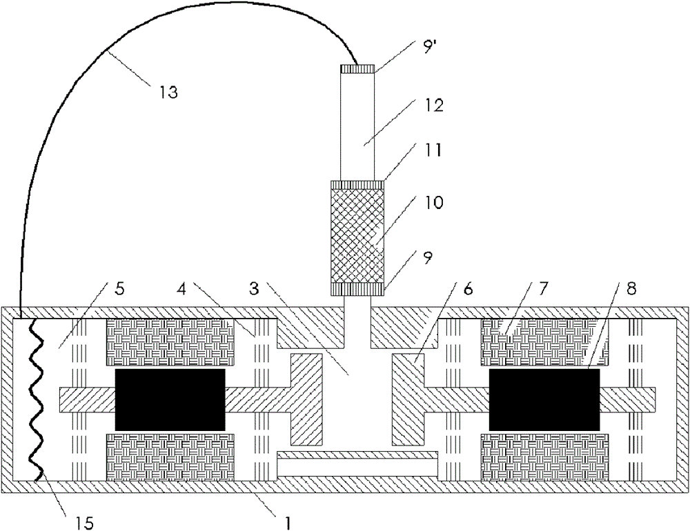
Embodiment 2

[0025] The traveling wave circuit pulse tube refrigerator driven by the linear compressor of the present embodiment, such as image 3 As shown, the compressor therein is also a double-linear compressor structure opposite to the left and right, and its structure is basically the same as that of Embodiment 1. The difference from Embodiment 1 is that an elastic diaphragm 15 is installed in the back chamber 5. This It is mainly to suppress the DC flow in the refrigerator; if there is no elastic membrane 15, the gas flowing into the back cavity 5 from the inertial tube 13 can pass through the piston and the compressor shell (more precisely, it should be The small gap between cylinders) enters the front cavity 3, and then enters the radiator, regenerator, cold head, pulse tube, secondary radiator, inertia tube, and finally returns to the back cavity. To the cold head, it will inevitably cause a large loss of cooling capacity. Therefore, installing the elastic diaphragm in the back c...

Embodiment 3

[0027] Embodiment 3: The traveling wave circuit pulse tube refrigerator driven by the linear compressor of this embodiment is composed of Figure 4 shown. In this embodiment, the regenerator 10 and the pulse tube 12 of the cold finger adopt a coaxial structure design, and the two are located on the same side of the cold head 11, so that the load to be cooled can be conveniently installed on the other end surface of the cold head . The regenerator 10 is designed as a ring structure, which just surrounds the outside of the vessel 12. The inertia tube 13 passes through the front cavity 3 of the compressor and communicates with the back cavity 5. If the inertia tube 13 is longer, it can also be directly coiled around the back cavity 5 middle.


PUM


Abstract

The invention discloses a linear compressor-driven travelling wave loop pulse tube refrigerator, which comprises a cold finger and a linear compressor, wherein the cold finger consists of a travelling wave loop pulse tube refrigerator and an inertia tube; a piston is used for partitioning the internal space of the linear compressor into a front cavity and a back cavity; a mover, a stator and a plate spring are positioned in the back cavity; the front cavity is communicated with a primary radiator, a heat regenerator, a cold head, a pulse tube and a secondary radiator in the travelling wave loop pulse tube refrigerator in sequence; and one end of the inertia tube is connected with the secondary radiator, and the other end of the inertia tube is communicated with the back cavity. According to the characteristics of large back cavity size and small pressure fluctuation of the linear compressor, the conventional air reservoir is removed, a travelling wave loop is formed by directly communicating the inertia tube with the back cavity, and the back cavity of the compressor plays a role in replacing the air reservoir; meanwhile, direct current flow can be suppressed, an elastic membrane for partitioning the back cavity into a front cavity front part and a back cavity back part can be arranged in the back cavity, and the inertia tube is communicated with the back part of the back cavity; a direct current channel is blocked, and the refrigerating performance of the refrigerator is kept; and the structure is more compact, and practical application is more facilitated.

Description

field of invention [0001] The present invention mainly relates to refrigerators in the field of refrigeration and low temperature, and in particular to a traveling wave circuit driven by a linear compressor that uses a compressor back chamber to replace an air reservoir in a pulse tube refrigerator to form a traveling wave circuit and reduce system volume. tube refrigerator. Background technique [0002] Pulse tube refrigerator is a popular research object of cryogenic refrigerator in recent years, because of its small size, high efficiency, simple structure and long life, it has a very wide application prospect in aerospace, military and other fields. Traditional pulse tube refrigerators such as figure 1 As shown, it is mainly composed of a compressor and a cold finger. Cold fingers mainly include radiators, regenerators, cold heads, pulse tubes, secondary radiators, inertia tubes, gas storage and other components; compressors mainly include shells, pistons, movers, stato...

Claims


Application Information

Patent Timeline
IPC IPC(8): F25B9/14
Inventor 胡剑英罗二仓李海冰王晓涛
Owner TECHNICAL INST OF PHYSICS & CHEMISTRY - CHINESE ACAD OF SCI
Why Eureka
Try Eureka