
Control terminal and system for indoor temperature

A technology for indoor temperature and control terminals, applied in the direction of temperature control, control/regulation system, non-electric variable control, etc., can solve the problems of no low-cost implementation scheme, high situation dependence, high implementation cost, and achieve low cost and high implementation cost. Simple technology and low power consumption

Inactive Publication Date: 2012-10-24
王博思
View PDF4 Cites 10 Cited by
  • Summary
  • Abstract
  • Description
  • Claims
  • Application Information

AI Technical Summary

Problems solved by technology

[0005] (1) It is highly dependent on the home computer, home LAN and Internet construction, the system implementation scheme is complicated, and the implementation cost is high, which is impossible for most families;
[0006] (2) There is no unified implementation standard, so it is difficult to popularize and apply;
[0007] (3) There is no low-cost implementation solution for home temperature regulation and control alone

Method used


Image

  • Control terminal and system for indoor temperature
  • Control terminal and system for indoor temperature
  • Control terminal and system for indoor temperature

Examples


Embodiment Construction

[0038] The specific implementation manners of the present invention will be further described in detail below in conjunction with the accompanying drawings and embodiments. The following examples are used to illustrate the present invention, but are not intended to limit the scope of the present invention.

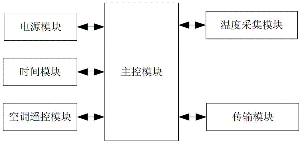
[0039] like figure 1 As shown, the indoor temperature control terminal of this embodiment includes: a power supply module, a main control module, a temperature acquisition module, an analog-to-digital conversion module, and a transmission module. The power supply module, temperature acquisition module, analog-to-digital conversion module and transmission module are all connected to the main control module.

[0040] The temperature collection module collects the indoor temperature in real time, and sends the collected temperature to the main control module.

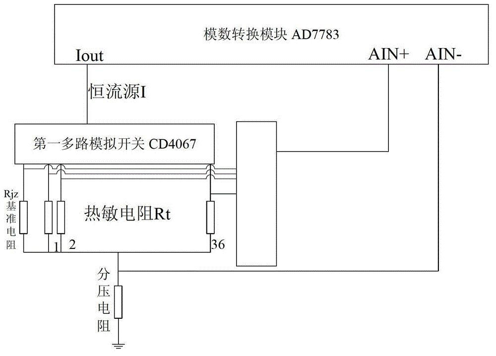
[0041] The temperature acquisition module of this embodiment is as figure 2 As shown, including: temperature sig...


PUM


Abstract

The invention discloses a control terminal for indoor temperature and relates to the fields of automatic control and electronics. The control terminal comprises a main control module, a temperature acquisition module, a transmission module, an air-conditioner remote control module, a time module and a power supply module, wherein the temperature acquisition module is connected with the main control module and is used for acquiring the indoor temperature in real time and transmitting the indoor temperature to the main control module; the transmission module is connected with the main control module and is used for transmitting the current indoor temperature or abnormal information exceeding the preset temperature range to a mobile terminal under the control of the main control module, receiving a temperature control instruction transmitted by the mobile terminal and transmitting the temperature control instruction to the main control module; the air-conditioner remote control module is connected with the main control module and is used for controlling the indoor temperature according to the temperature control instruction under the control of the main control module; the time module is connected with the main control module and is used for providing an accurate clock and temperature acquisition timing time for the main control module; and the power supply module is connected with the main control module and is used for supplying power to the modules. According to the control terminal disclosed by the invention, the remote mobile control for the indoor temperature is realized at low cost.

Description

technical field [0001] The invention relates to the fields of automatic control and electronic technology, in particular to an indoor temperature control terminal and system. Background technique [0002] The tremendous development of sensing technology, electronic technology and communication technology has changed the way people work and communicate, but they are rarely applied in people's daily life and home environment. At the same time, the emergence of various information home appliances has increased the variety, which has instead dispersed the scope of people's control. This decentralized control has brought inconvenience to people. In this way, the family, as one of the basic units of society, has almost become an isolated island in the information age. As people pay more and more attention to the home environment, people begin to consider building an information network in the home environment, combining various information appliances and communication products to...

Claims


Application Information

Patent Timeline
IPC IPC(8): G05D23/24
Inventor 王博思
Owner 王博思
Learn More