3D (Three-dimensional) display method and display device

A display method and display device technology, applied in the field of 3D display, capable of solving problems such as high power consumption and small viewing angle of 3D panels

Inactive Publication Date: 2012-10-24
BOE TECH GRP CO LTD
View PDF13 Cites 10 Cited by
  • Summary
  • Abstract
  • Description
  • Claims
  • Application Information

AI Technical Summary

Problems solved by technology

[0004] Embodiments of the present invention provide a 3D display method and a display device, which are used to solve the problems in the prior art that the viewing angle of the 3D panel in the vertical direction is small and the power consumption is large

Method used


Image

  • 3D (Three-dimensional) display method and display device
  • 3D (Three-dimensional) display method and display device
  • 3D (Three-dimensional) display method and display device

Examples


Embodiment 1

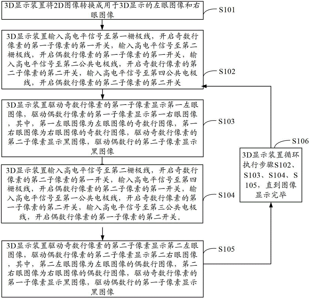
[0069] In a 3D display method provided by an embodiment of the present invention, each pixel in a display panel includes a first sub-pixel and a second sub-pixel, and the method includes:

[0070] Step a: Drive the first sub-pixels of odd-numbered rows of pixels to display the first left-eye image, and drive the first sub-pixels of even-numbered rows of pixels to display the first right-eye image, wherein the first left-eye image is an odd number of left-eye images row image, the first right-eye image is an odd-numbered row image of the right-eye image, driving the second sub-pixels of the odd-numbered rows of pixels to display a black image, and driving the second sub-pixels of the even-numbered rows to display a black image;

[0071] Step b: driving the second sub-pixels of the odd-numbered rows of pixels to display a second left-eye image, and driving the second sub-pixels of the even-numbered rows of pixels to display a second right-eye image, wherein the second left-eye im...

Embodiment 2

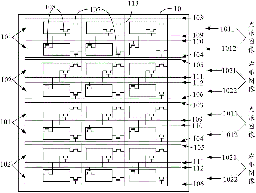
[0135] An embodiment of the present invention provides a 3D display device 1, such as Figure 4 shown, including:

[0136] The display panel 10 includes multiple rows and columns of pixels arranged in an array, the multiple rows of pixels include odd-numbered rows of pixels and even-numbered rows of pixels, and each pixel includes a first sub-pixel and a second sub-pixel: each of the display panels The sub-pixel also includes a first switch and a second switch: the display panel further includes: a first gate line, the first gate line is connected to the gate of the first switch of the first sub-pixel of the odd-numbered row of pixels connection; the second gate line, the second gate line is connected to the gate of the first switch of the second sub-pixel of the odd row of pixels; the third gate line, the third gate line is connected to the The first sub-pixel of the pixel in the even row is connected to the gate of the first switch; the fourth gate line is connected to the ...


PUM


Abstract

The embodiment of the invention discloses a 3D (Three-dimensional) display method and a display device, relating to the technical field of 3D display and aiming at enlarging a visual angle of a 3D display panel in the vertical direction and reducing the power consumption. The method comprises the following steps: step a, driving a first sub-pixel of an odd-numbered line pixel to display a first left eye image, driving a first sub-pixel of an even-numbered line pixel to display a first right eye image, driving a second sub-pixel of the odd-numbered line pixel to display a second left eye image, and driving a second sub-pixel of the even-numbered line to display a dark image; and step b, driving a second sub-pixel of the odd-numbered line pixel to display a second left eye image, driving a second sub-pixel of the even-numbered line pixel to display a second right eye image, wherein the second left eye image is the even-number line image of the left eye image, the second right eye image is the even-numbered line image of the right eye image; driving the first sub-pixel of the odd-numbered line pixel to display the dark image; and driving the first sub-pixel of the even-numbered line to display the dark image; and executing the steps a and b circularly until the image is displayed completely.

Description

technical field [0001] The present invention relates to the technical field of 3D display, in particular to a 3D display method and a display device. Background technique [0002] In recent years, most entertainment programs such as TV programs and movies currently use 2D (Two Dimensions, two-dimensional) images, and people are increasingly dissatisfied with 2D images. 3D (Three Dimensions, three-dimensional) stereoscopic images are the future image display. The inevitable trend. The principle of 3D image display is to make the left eye see the left eye image, and the right eye see the right eye image, wherein the left and right eye images are a pair of stereoscopic image pairs with displacement difference, so that the viewer can watch objects similar to The actual image of the three-dimensional image stereoscopic image. [0003] Polarized glasses-type 3D display is a mainstream technology in the field of 3D display today. It is loved by everyone for its features such as n...

Claims


Application Information

Patent Timeline
IPC IPC(8): H04N13/00G02B27/22G09G3/20
CPCH04N13/04H04N13/315H04N13/31H04N13/398
Inventor 吕敬
Owner BOE TECH GRP CO LTD
Why Eureka
Try Eureka