

Ophthalmic apparatus, and method of controlling ophthalmic apparatus
An equipment, ophthalmology technology, applied in the fields of eye testing equipment, ophthalmoscope, medical science, etc., can solve problems such as limiting image brightness level, reducing the amount of retinal illumination, and deteriorating image quality.
- Summary
- Abstract
- Description
- Claims
- Application Information
AI Technical Summary
Problems solved by technology
Method used
Image

Examples
no. 1 example
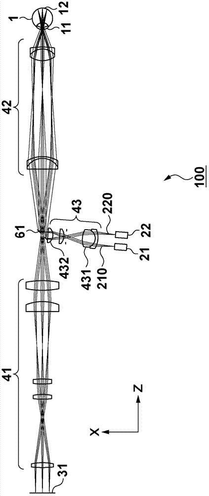
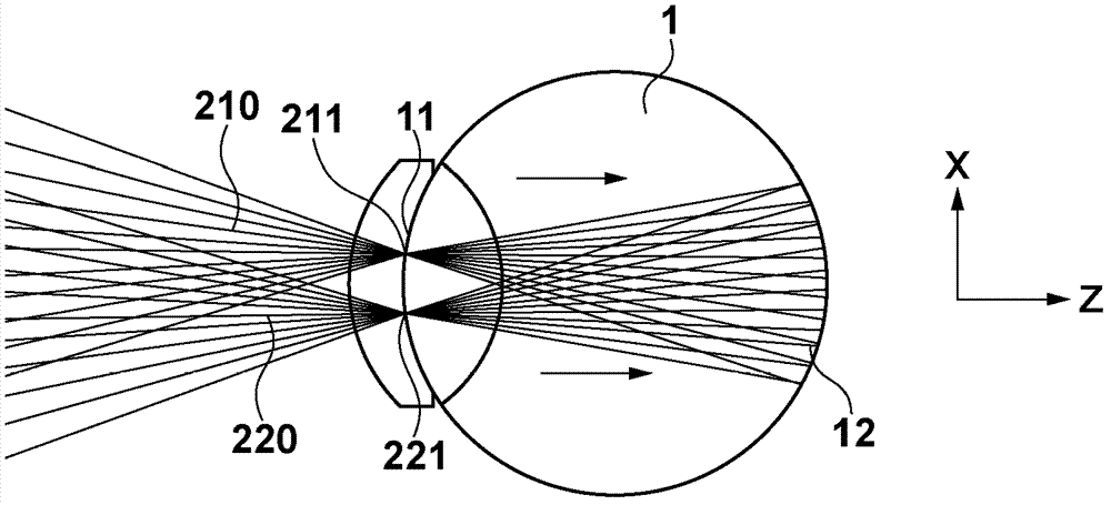
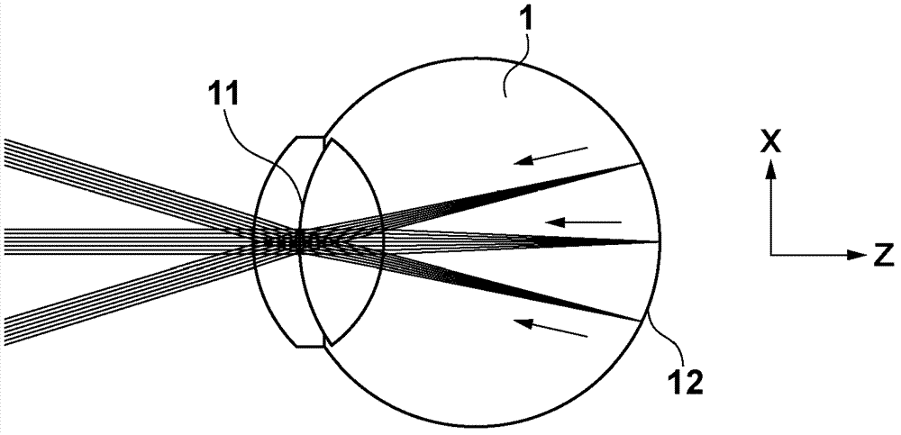
[0029] will refer to figure 1 The structure of the ophthalmic apparatus (fundus camera 100 ) according to the first embodiment is explained. The fundus camera 100 irradiates the subject's eye 1 with illumination light from two light sources 21 and 22 via an illumination optical system 43 and an eyepiece optical system 42 (the combination of which is hereinafter referred to as an illumination beam optical system (first optical system)). Retina 12. This apparatus has a configuration for making reflection / backlight as return light from the retina 12 via an eyepiece optical system 42 and an imaging optical system 41 (hereinafter, their combination is referred to as an imaging optical system (second optical system)). The scattered light forms an image on the imaging element 31 to acquire a fundus image (two-dimensional image) (image generation process). In this case, the illumination beam optical system and the imaging optical system have a common portion (eyepiece optical system...
no. 2 example
[0042] will then refer to Figure 5 An ophthalmic apparatus ( SLO101 ) according to the second embodiment is explained. The SLO 101 irradiates the retina 12 with linear illumination light, and scans the light in a direction perpendicular to the direction of the line. The apparatus is configured to acquire a two-dimensional image by measuring reflected / backscattered light as return light using a light-receiving sensor in a matrix form including a plurality of light-receiving elements arranged in at least one-dimensional direction. The coordinates in this case are the same as figure 1 , and the linear illumination on the retina 12 coincides with the x-z section.
[0043] In order to form such illumination light, the illumination light propagating to the retina 12 needs to have divergence in the line direction (x direction) of the linear illumination on the retina 12 and a direction perpendicular to the line direction (direction of scanning illumination light: y direction). ) ...
no. 3 example
[0054] will refer to Figure 8 The structure of the ophthalmic apparatus according to the third embodiment is explained. This embodiment exemplifies the ophthalmic imaging apparatus 102 including OCT and SLO. As in the first and second embodiments, the SLO includes an illumination optical system 43 , an eyepiece optical system 42 and an imaging optical system 41 . In addition, OCT is based on the spectral domain (SD) method, wherein the interferometer is composed of a light source 70 , a sampling optical system that shares the eyepiece optical system 42 with the SLO, a reference optical system 72 , and a beam splitter 73 .
[0055] Both SLO and OCT in this embodiment use the method of two-dimensionally scanning small light spots on the retina in the vertical and horizontal directions. The SLO allows the operator to simultaneously observe the OCT tomographic image (B-scan image) and the frontal image in correlation with each other while monitoring the frontal image of a wide ...
PUM
 Abstract
Description
Claims
Application Information