High current inductor assembly

A technology for inductor windings and inductors, which is applied in the direction of inductors, fixed inductors, transformers/inductor coils/windings/connections, etc., which can solve the problem of not firmly connecting the circuit board, the circuit board cannot be installed on the same plane, and occupies a large area Space and other issues

Active Publication Date: 2012-10-31
村田电源
View PDF4 Cites 13 Cited by
  • Summary
  • Abstract
  • Description
  • Claims
  • Application Information

AI Technical Summary

Problems solved by technology

This leads to the problem that the size of the circuit board must be significantly increased in order to provide sufficient space for both the inductor assembly and other required electronic components to be mounted on the circuit board
Therefore, such a configuration leads to the problem that each inductor component takes up a lot of space on the circuit board, which obviously reduces th...

Method used


Image

  • High current inductor assembly
  • High current inductor assembly
  • High current inductor assembly

Examples


Embodiment Construction

[0018] Preferred embodiments of the present invention are described below with reference to the accompanying drawings.

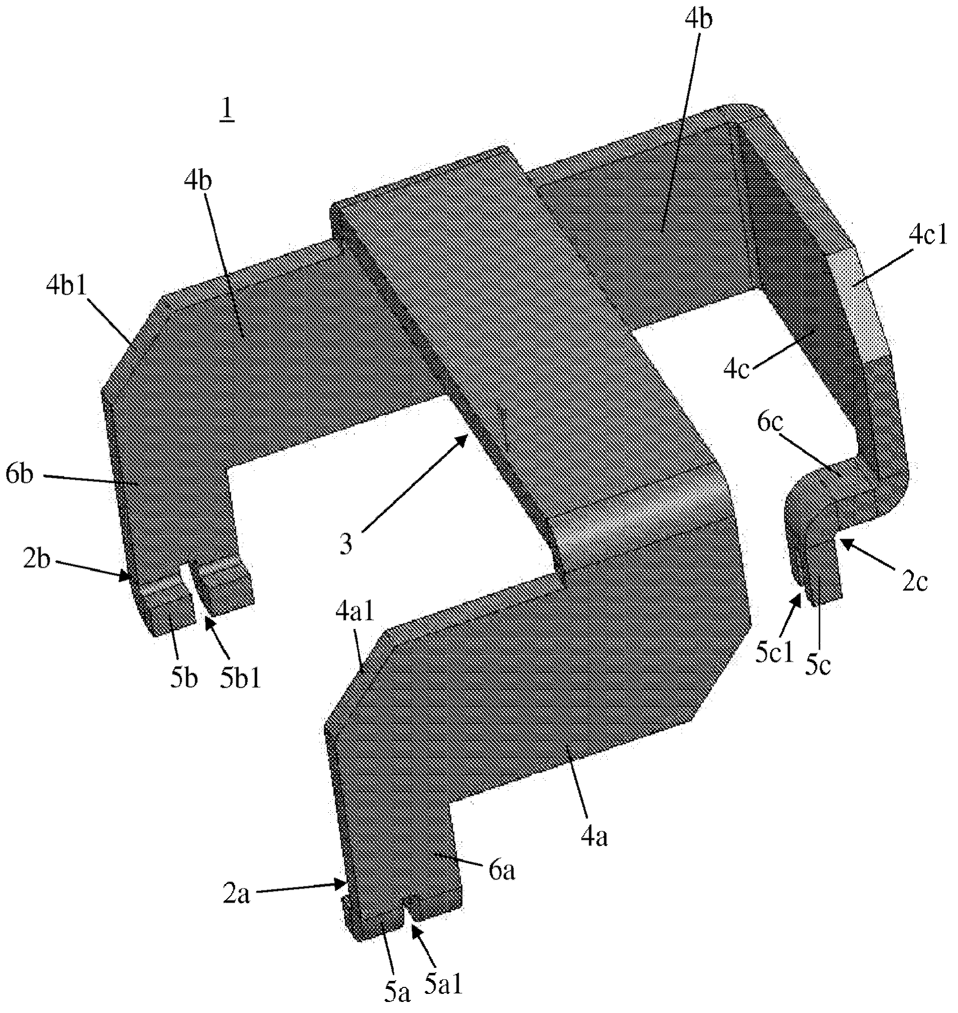
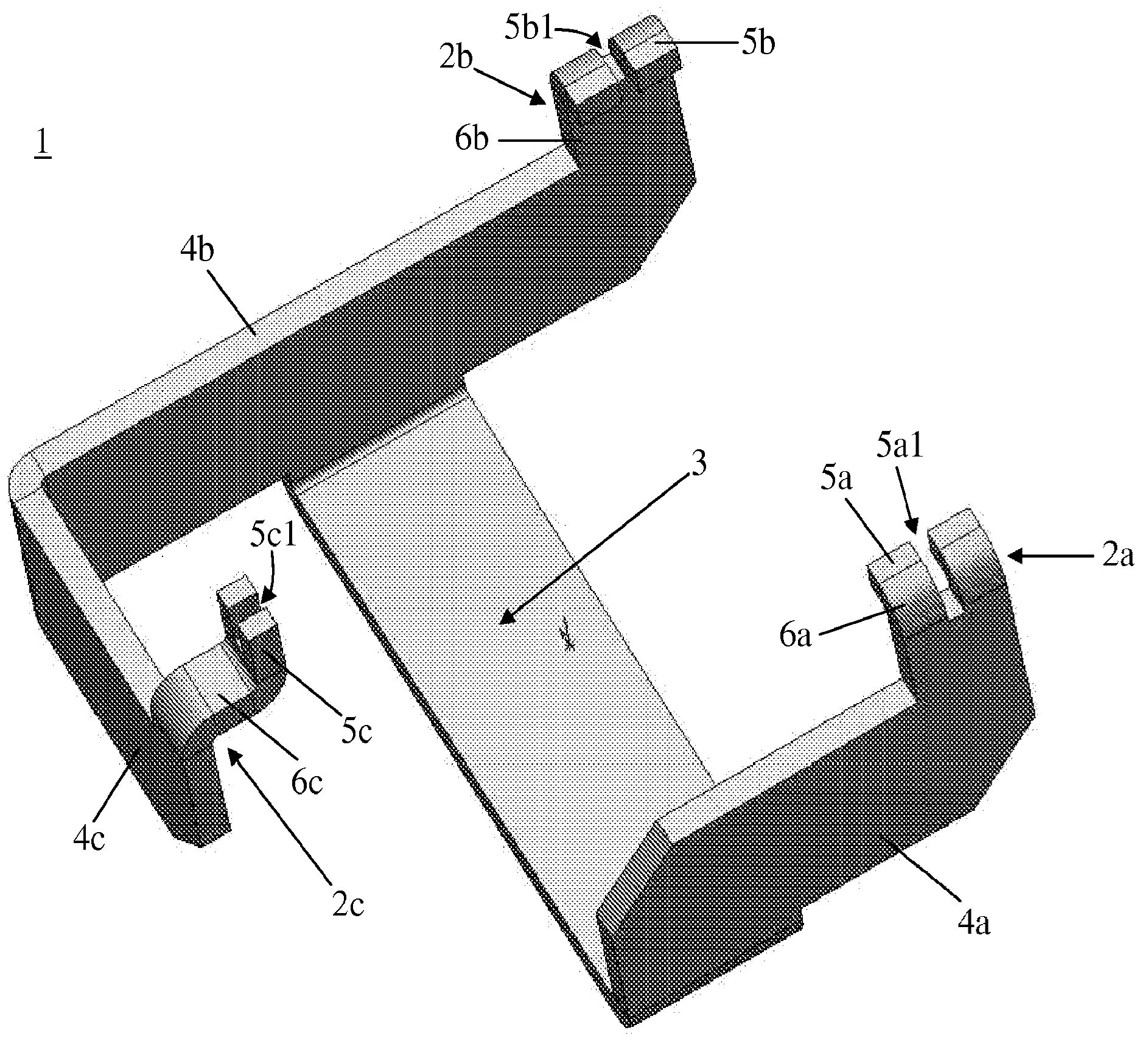
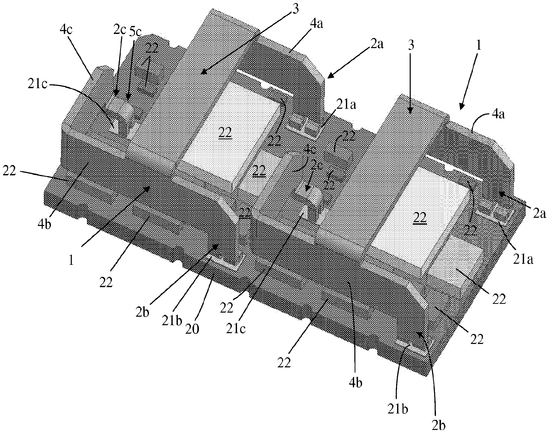
[0019] as in Figure 1-4 As shown in , an inductor winding 1 according to a preferred embodiment of the present invention preferably comprises a middle part 3 and first, second and third legs 2a, 2b and 2c, preferably, for example, first, second and third legs 2a, 2b and 2c are arranged in a tripod structure and are connected to the middle part 3 by first, second and third arms 4a, 4b and 4c. The middle part 3 extends between the first arm 4a and the second arm 4b, and is connected to the first arm 4a and the second arm 4b. Preferably, one end of the middle part 3 is connected to the end of the first arm 4a, and the other end of the middle part 3 is connected to the central part of the second arm 4b. However, the intermediate portion 3 may be arranged to extend between any suitable portions of the first, second and third arms 4a, 4b and 4c, and to connect ...


PUM


Abstract

An inductor winding includes first, second, and third arms, a middle portion extending between and connected to at least two of the first, second, and third arms and arranged to support a winding core mounted thereon, and first, second, and third legs extending downwardly from the first, second and third arms, respectively, and arranged to be mounted on a circuit board. The first, second, and third legs are arranged to provide three-point contact with the circuit board, and the inductor winding is arranged to provide a space between a bottom surface of the winding core mounted on the middle portion and an upper surface of electronic components mounted on the circuit board.

Description

technical field [0001] The present invention relates to inductor assemblies, and in particular, to an inductor winding structure provided in a high current inductor assembly on which an inductor core is mounted. Background technique [0002] Inductor components are commonly used in many high current applications such as switching power supply units. High current inductor components are relatively large and thus occupy a relatively large portion and, in many cases, a major portion of the circuit board on which they are mounted. This leads to the problem that the size of the circuit board must be significantly increased in order to provide sufficient space for both the inductor assembly to be mounted on the circuit board and other required electronic components. [0003] Known inductor assemblies are configured such that the bottom surface of the inductor core is in contact with or arranged in close proximity to the surface of the circuit board. With this configuration, the ...

Claims


Application Information

Patent Timeline
IPC IPC(8): H01F17/00H01F27/28
CPCH01F27/2847H01F27/2852H01F27/306H01F2027/2861
Inventor 丹尼尔·布伦南
Owner 村田电源
Why Eureka
Try Eureka