
Combined arm joint of crane, crane and mounting method of crane

An installation method and a crane technology, which are applied to cranes, transportation and packaging, and load hanging components, etc., can solve the problems of complicated installation process and many assembly parts, and achieve the goals of reducing high-altitude operations, simplifying production and installation, and facilitating safe production Effect

Active Publication Date: 2012-11-07
ZOOMLION HEAVY IND CO LTD
View PDF5 Cites 4 Cited by
  • Summary
  • Abstract
  • Description
  • Claims
  • Application Information

AI Technical Summary

Problems solved by technology

[0010] The purpose of the present invention is to provide a combined jib section of a crane, a crane and a crane installation method, so as to solve the technical problems of the prior art that there are many assembly parts on the upper part of the crane and the installation process is relatively complicated

Method used


Image

  • Combined arm joint of crane, crane and mounting method of crane
  • Combined arm joint of crane, crane and mounting method of crane
  • Combined arm joint of crane, crane and mounting method of crane

Examples


Embodiment Construction

[0029] The present invention will be described in detail below with reference to the accompanying drawings and examples. It should be noted that, in the case of no conflict, the embodiments in the present application and the features in the embodiments can be combined with each other.

[0030] The combined jib section of the crane of the present invention is particularly suitable for tower cranes.

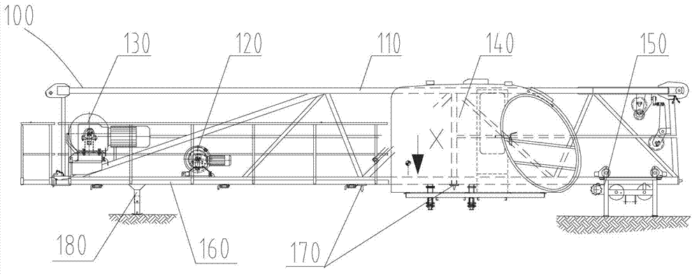
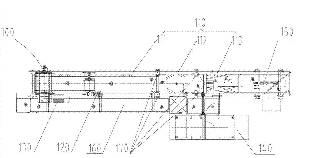
[0031] Such as Figure 2 to Figure 4 As shown, the combined jib section 100 mainly includes a jib section body 110 and a connecting portion 170 disposed on the jib section body 110 , wherein the connecting portion 170 is located between the opposite first end and the second end of the jib section body 110 , It is used to connect with the upper end of the slewing assembly 300 of the crane; in the boom section body 110, the part where the connecting part 170 is located forms the slewing tower body segment 112, and the part between the slewing tower body segment 112 and the first end...


PUM


Abstract

The invention provides a combined arm joint of a crane, the crane and a mounting method of the crane. The combined arm joint comprises an arm joint body (110) and a connecting part (170) arranged on the arm joint body (110), wherein the connecting part (170) is located between a first end and a second end of the arm joint body (110) opposite to each other and used for being connected with the upper end of a rotary assembly (300) of the crane; and in the arm joint body (110), a rotary tower body section (112) is formed in the connecting part (170), a balanced arm joint section (111) as a first arm joint of a balanced arm of the crane is formed between the rotary tower body section (112) and the first end, and a lift arm section (113) as a first arm joint of a lift arm of the crane is formed between the rotary tower body section (112) and the second end. According to the combined arm joint of the crane, the quantity of parts at the upper part of the tower crane is reduced and the design, manufacturing and mounting operations are simplified.

Description

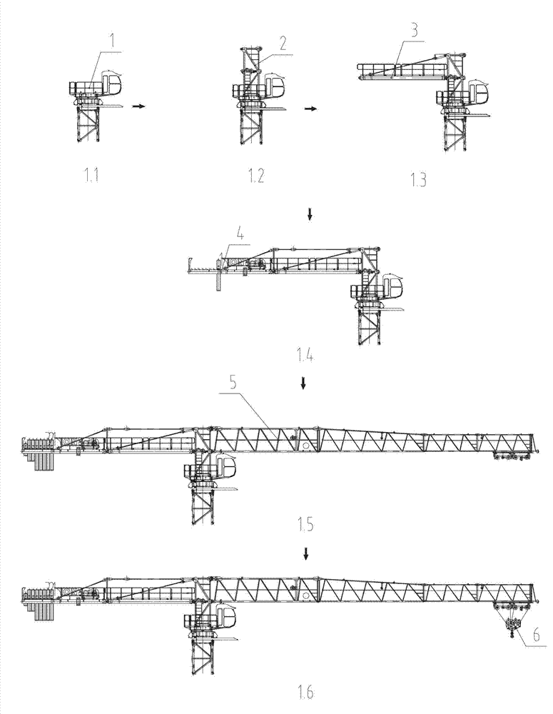
technical field [0001] The invention relates to the field of hoisting machinery, in particular to a combined jib section of a crane, a crane and a method for installing the crane. Background technique [0002] In the prior art, the first section of the balance jib section, the slewing tower body and the first section of the boom section of the tower crane are arranged separately. The installation process of this tower crane is as follows: figure 1 shown, where figure 1 .1~1.6 represent respectively: [0003] 1.1. Install tower body and slewing assembly 1; [0004] 1.2. Install the slewing tower body 2 on the slewing assembly 1; [0005] 1.3. Install the first balance jib section 3 on the rear side of the slewing tower body 2; [0006] 1.4. Install the second section of the balance arm section 4 and part of the counterweight (such as a counterweight); [0007] 1.5. Install the boom 5 and the remaining balance weight on the front side of the slewing tower body 2; [000...

Claims


Application Information

Patent Timeline
IPC IPC(8): B66C23/64B66C23/66B66C23/82B66C13/54
Inventor 钱建军李建华孙旭国
Owner ZOOMLION HEAVY IND CO LTD
Learn More