Flood protective dam and framework thereof
A skeleton and frame technology, applied in the field of water conservancy engineering, can solve problems such as non-recovery, dyke burst, and dyke cannot be moved, and achieves the effect of convenient maintenance and low maintenance cost.
- Summary
- Abstract
- Description
- Claims
- Application Information
AI Technical Summary
Problems solved by technology
Method used
Image

Examples
Embodiment Construction
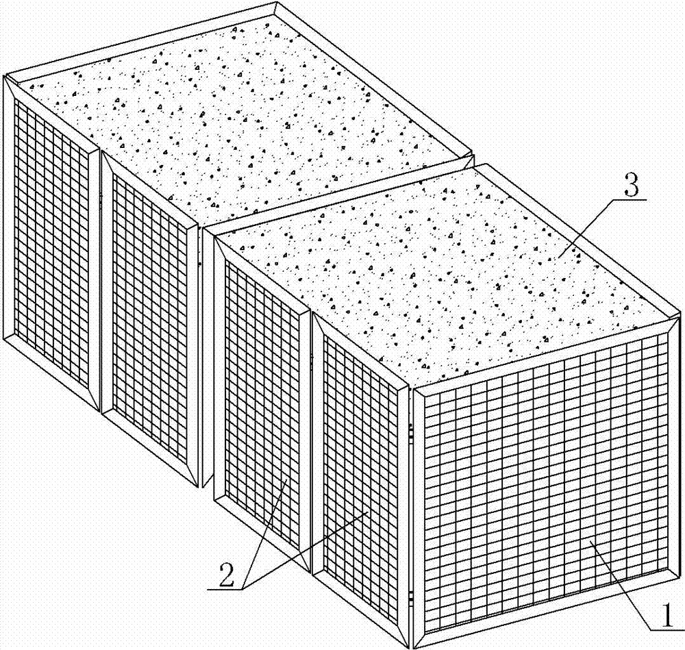
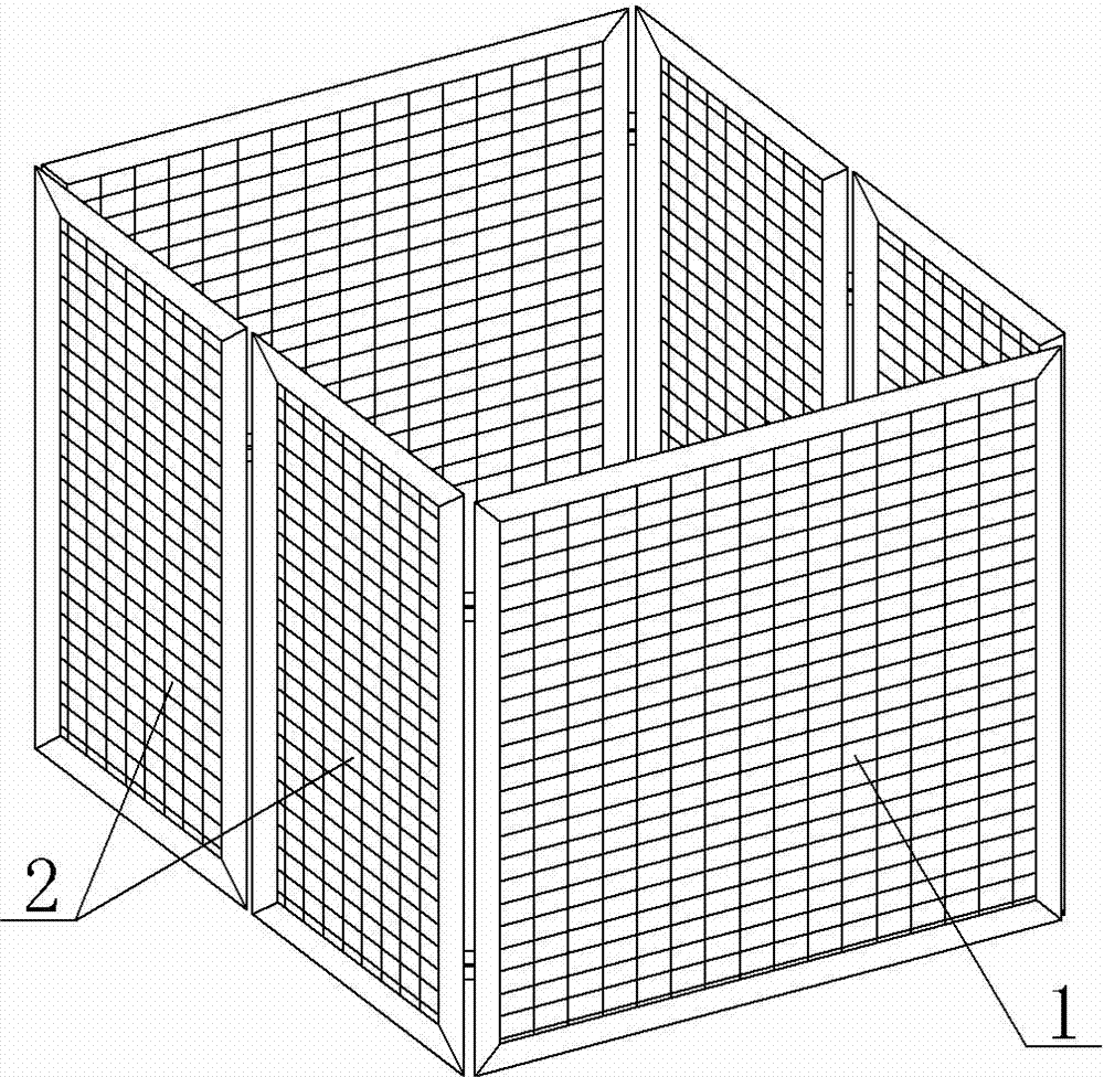
[0024] A kind of embodiment of flood control damming, in figure 1 , combined with figure 2 and image 3 , the skeleton of this flood control dam is composed of a series of supporting frames 1 and connecting frames 2, the supporting frames 1 are all arranged in parallel, and two sets of connecting frames are arranged between two adjacent supporting frames 1, and one of the connecting frames It is arranged on one side of the supporting frame 1, and another group of connecting frames is arranged on the other side of the supporting frame 1. Each group of connecting frames has two connecting frames 2, and the length and width of the two connecting frames 2 are correspondingly equal. The two connecting frames 2 are rotatably assembled together on one side, and the other sides of the two connecting frames 2 are rotatably assembled with corresponding two adjacent support frames 1 respectively. In this way, the two groups of connecting frames connect the adjacent two supporting fram...
PUM
 Abstract
Description
Claims
Application Information