
Resonant cavity device, and system and device using resonant cavity device

A resonant cavity and device technology, applied in the field of lasers, can solve problems such as the inability to realize high-Q transfer cavity at the same time, and the inability to realize broadband high-reflectivity coating, etc., to achieve high-quality laser line width narrowing and stable transmission, stable laser output, The effect of achieving stable output

Inactive Publication Date: 2012-11-07
NAT INST OF METROLOGY CHINA
View PDF3 Cites 11 Cited by
  • Summary
  • Abstract
  • Description
  • Claims
  • Application Information

AI Technical Summary

Benefits of technology

This patented invented new type of resonance device allows multiple oscillations within each unit cell (a single chip) to occur simultaneously without affecting other units). By combining these individual waves into an identically distributed wave packet called a train of light pulses, cohabitation between them becomes easier than before. Additionally, there are also improvements made over existing methods like phase locked loop techniques where only certain frequencies have been effectively locked together. Overall, this innovation improves both stability and performance during long distance communication applications such as satellite broadcast systems.

Problems solved by technology

This patented technical problem addressed in this patents relates to improving the performance of small semiconducer (semi) diodes for applications that require narrower lines than previous designs have been developed but they still suffer from issues like instability caused by poor coatings or lack of consistently effective reflection films over multiple wavelengage ranges.

Method used


Image

  • Resonant cavity device, and system and device using resonant cavity device
  • Resonant cavity device, and system and device using resonant cavity device
  • Resonant cavity device, and system and device using resonant cavity device

Examples


Embodiment Construction

[0040] In order to make the object, technical solution and advantages of the present invention clearer, the present invention will be described in further detail below in conjunction with specific embodiments and with reference to the accompanying drawings.

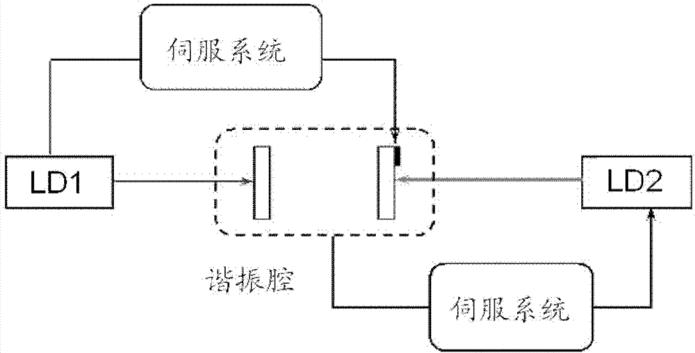
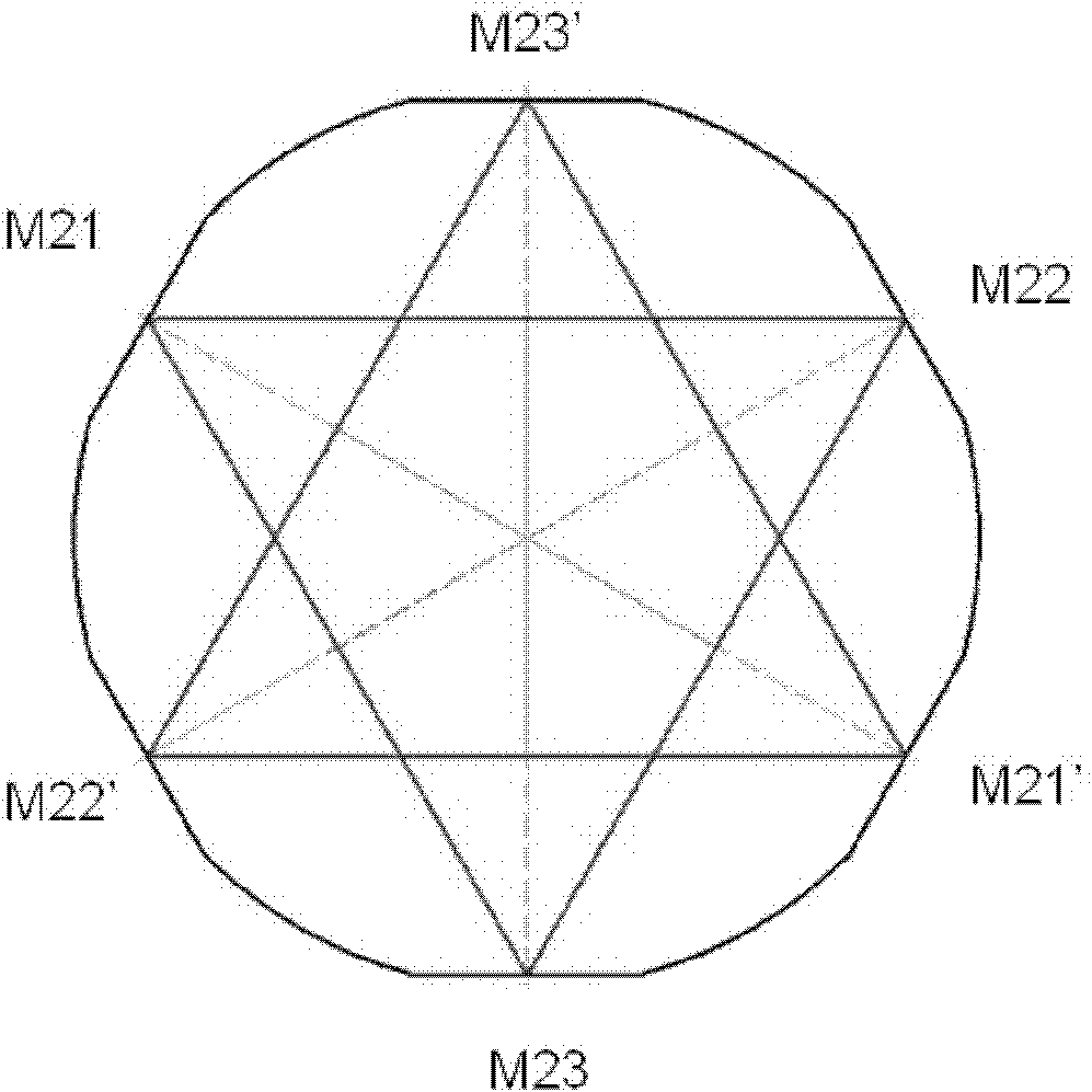
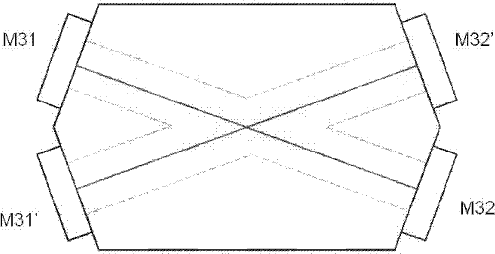
[0041] An embodiment of the present invention provides a resonant cavity device. In the device, multiple optical reflective surfaces constituting the resonant cavity are arranged on a single substrate. The base is in the shape of a polyhedron. The multiple optical reflective surfaces form at least two independent resonant cavity.

[0042] In this way, by simultaneously setting two or more resonant cavity structures on an integrally fixed optical element, the simultaneous use, comparison, and transfer of lasers with different wavelengths and different Q values ​​can be realized. When the resonant cavity device is applied to a laser, it can well narrow the laser line width and stabilize the output.

[0043]Wherein, the opt...


PUM


Abstract

The invention discloses a resonant cavity device, wherein a resonant cavity is formed by a plurality of optical reflecting surfaces which are arranged on a single substrate and of polyhedral shapes. At least two mutually independent resonant cavities are formed by a plurality of optical reflecting surfaces. In addition, based on the resonant cavity device, the invention also provides a system and for a device which both use the resonant cavity device, the resonant cavity device is used as an optical feedback device for pressing and narrowing the width of a laser ray. With the adoption of the system and the device using the resonant cavity device, the laser has the characteristics of wide narrow ray, stable output, simple operation and the like. In addition, by utilizing the resonant cavity device, the stable transmission of laser frequency is realized, and meanwhile, the stable radio frequency signal output is obtained.

Description


Claims


Application Information

Patent Timeline
Owner NAT INST OF METROLOGY CHINA
Learn More