Magnetic module formed by permanent magnet magnetic circuit and magnetic circuit transformational structure

A technology for converting structures and magnetic circuits, applied in electrical components, load hanging components, transportation and packaging, etc., can solve the problems of low magnetic circuit conversion efficiency and large magnetic loss, and achieve improved suction, improved operation efficiency, and improved operation process. Simple and convenient effects

Inactive Publication Date: 2012-11-07
HUNAN QIANHAO ELECTRICAL & MECHANICAL TECH DEV
View PDF3 Cites 4 Cited by
  • Summary
  • Abstract
  • Description
  • Claims
  • Application Information

AI Technical Summary

Problems solved by technology

[0002] In the field of permanent magnet lifting and magnetic clamping, the traditional structural form of translation and magnetic shaft chain transmission control has been adopted in China. Although permanent magnet lifting and magnetic clamping can be realized, there is a large loss of magnetic force and the conversion efficiency of the magnetic circuit is high. low disadvantage

Method used


Image

  • Magnetic module formed by permanent magnet magnetic circuit and magnetic circuit transformational structure
  • Magnetic module formed by permanent magnet magnetic circuit and magnetic circuit transformational structure
  • Magnetic module formed by permanent magnet magnetic circuit and magnetic circuit transformational structure

Examples


Embodiment Construction

[0012] The present invention will be further elaborated below in conjunction with the accompanying drawings and specific implementation examples.

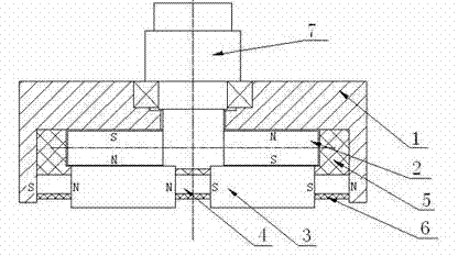
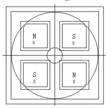
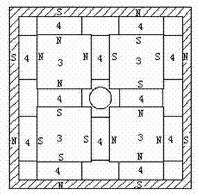
[0013] Such as figure 1 , 2 , 3. It can be seen that the magnetic module is composed of cover plate 1, turntable assembly 2, magnetic pole 3, permanent magnet steel 4 for magnetic pole, upper fixed shell 5, lower fixed shell 6, transmission shaft assembly 7, and permanent magnetic steel 8 for turntable. The transmission shaft assembly 7 is installed on the cover plate 1, and the lower end extends into the inside of the cover plate. The turntable assembly 2 is connected and fixed with the lower end of the drive shaft through a key. The permanent magnet steel 8 for the turntable is mounted on the turntable and clamped and fixed by the turntable. It can be seen from the figure that the permanent magnet steel for the turntable is divided into 4 parts on the turntable. The polarity of a part of the permanent magnet steel is upper N and...


PUM


Abstract

The invention relates to a magnetic module formed by a permanent magnet magnetic circuit and a magnetic circuit transformational structure, the magnetic module is characterized by consisting of a cover board, a rotary shaft component, a turntable component, a magnetic pole, an upper fixed shell, a lower fixed shell, a permanent magnet steel for the magnetic pole and a permanent magnet steel for turntable, wherein the turntable component is provided with four permanent magnet steels, and the adjacent magnetic poles are opposite; the lower part of the turntable component is provided with four corresponding magnetic poles; the four sides of each magnetic pole are provided with permanent magnet steels, each magnetic pole has a fixed polarity. When the polarity at the lower part of the turntable permanent magnet steel is the same as that of the corresponding magnetic pole, the whole magnetic module outwards generates a suction force, when the turntable component is rotated to 90 degrees, the polarity of the turntable permanent magnet steel and the polarity of the corresponding magnetic pole are opposite, the suction is not outwards generated.

Description

technical field [0001] The invention relates to a magnetic module, in particular to a magnetic module composed of a permanent magnetic circuit and a magnetic circuit conversion structure. Background technique [0002] In the field of permanent magnet lifting and magnetic clamping, the traditional structural form of translation and magnetic shaft chain transmission control has been adopted in China. Although permanent magnet lifting and magnetic clamping can be realized, there is a large loss of magnetic force and the conversion efficiency of the magnetic circuit is high. low downside. Contents of the invention [0003] The purpose of the present invention is to provide a magnetic module composed of a permanent magnet magnetic circuit and a magnetic circuit conversion structure. The magnetic circuit structure and magnetic circuit conversion method are adopted to improve the efficiency and accuracy of the permanent magnet magnetic circuit in practical applications. [0004]...

Claims


Application Information

Patent Timeline
Patent Type & Authority Applications(China)
IPC IPC(8): H02N11/00B66C1/04
Inventor 王梅千陈代新
Owner HUNAN QIANHAO ELECTRICAL & MECHANICAL TECH DEV
Why Eureka
Try Eureka