Rotation transmission device and rotation device

A transmission and rotary drive technology, applied in transmissions, fluids using vibration, belts/chains/gears, etc., can solve the problems of time-consuming and labor-intensive magnetization, high manufacturing costs, and achieve low manufacturing costs, reduce wear and contact noise. , the effect of reducing contact pressure

Inactive Publication Date: 2012-11-14
NEW SHICOH MOTOR CO LTD
View PDF8 Cites 2 Cited by
  • Summary
  • Abstract
  • Description
  • Claims
  • Application Information

AI Technical Summary

Problems solved by technology

Therefore, when manufacturing these parts, for example, it is necessary to magnetize in the direction corresponding to the magnetic pole. Since magnetization in multiple directions is required, magnetization is time-consuming and labor-intensive. A special magnetizer is also required for magnetization.
[0004] For this reason, there is a problem that the production cost of parts such as active parts and driven parts is high

Method used


Image

  • Rotation transmission device and rotation device
  • Rotation transmission device and rotation device
  • Rotation transmission device and rotation device

Examples


Embodiment Construction

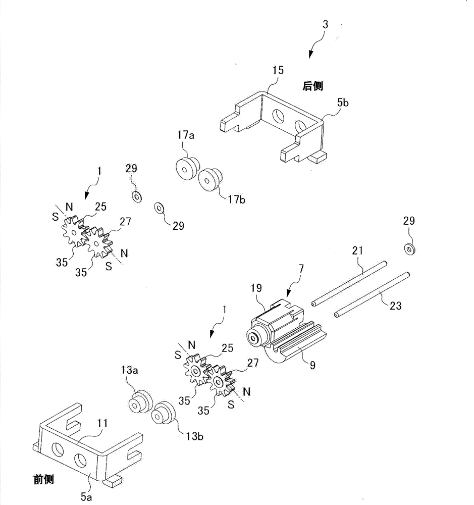
[0042] Hereinafter, each embodiment of the present invention will be described in detail. First, refer to the attached Figure 1 ~ Figure 4 , the first embodiment of the present invention will be described. The rotary transmission device 1 according to the first embodiment is a vibrating device 3 that is used on a mobile phone or the like and that vibrates when a signal is received.

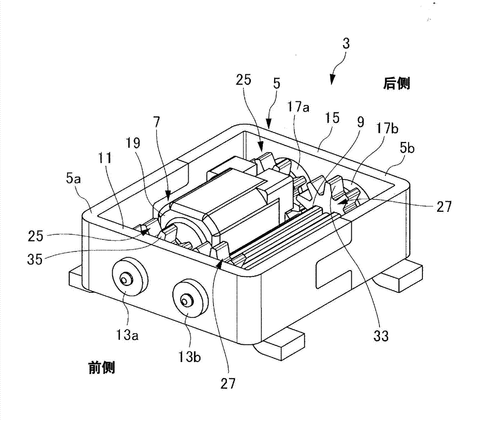
[0043] This vibration device 3 such as figure 2 and image 3 As shown, there is a housing 5, a motor 7 held in the housing 5, and an eccentric weight 9.

[0044] The casing 5 is divided into a front casing portion 5 a and a rear casing portion 5 b, and these are fitted and fixed to form an annular casing 5 .

[0045] Two bearings 13a, 13b are arranged side by side on the front side wall 11 of the cabinet 5, and bearings 17a, 17b are also provided on the rear side wall 15 facing the front side wall.

[0046] The motor 7 has a motor body 19 and a motor shaft 21 . The motor shaft 21 is press-...


PUM


Abstract

The invention provides a rotation transmission device and a rotation device which can easily be magnetized and manufacturing costs are low. The rotation transmission device (1) is provided with a driving gear (25) for rotating a driving shaft and a driven gear (27) meshed with the driving gear (25). Each gear (35) of the driving gear (25) and the driven gear (27) is respectively provided with different poles on one side (31) and the other side (32) in an axial direction; each gear (35) possesses a same pole in a peripheral direction. At positions where the driving gear (25) and the driven gear (27) are meshed, relative gear surfaces and poles are the same.

Description

technical field [0001] The present invention relates to a rotation transmission device for transmitting the rotation of driving parts such as gears and friction wheels to driven parts, and a vibration device using the rotation transmission device. Background technique [0002] In the rotary transmission device, Patent Document 1 (JP Unexamined Publication No. 6-51580) discloses a kind of different magnetic poles that alternate with each other in the circumferential direction of the outer circumference of the active member and the driven member. When different magnetic poles face each other, the rotation of the driving member is transmitted to the driven member. [0003] However, in Patent Document 1, in the driving member and the driven member, different magnetic poles are alternately formed in the circumferential direction of each outer peripheral portion. Therefore, when manufacturing these parts, for example, there must be magnetization in the direction corresponding to ...

Claims


Application Information

Patent Timeline
Patent Type & Authority Applications(China)
IPC IPC(8): F16H49/00B06B1/16
Inventor 白木学
Owner NEW SHICOH MOTOR CO LTD
Why Eureka
Try Eureka