Sealed unloading groove between valve body and valve joint plate

A technology of inter-plate sealing and unloading groove, which is applied in the hydraulic field, can solve problems such as tensile damage of connecting screws, high-pressure liquid injection, and large separation force between the valve body and the valve connecting plate, so as to avoid tensile damage and improve the structure. simple effect

Active Publication Date: 2012-11-14
BEIJING TIANMA INTELLIGENT CONTROL TECH CO LTD +1
View PDF9 Cites 0 Cited by
  • Summary
  • Abstract
  • Description
  • Claims
  • Application Information

AI Technical Summary

Problems solved by technology

[0002] In coal mine hydraulic support valves, there is often a plate connection between the valve body and the valve connection plate. In the prior art, this type of plate connection is provided with a rubber sealing ring at the connection. If the seal fails, the high-pressure liquid will flow through the entire The joint surface between the valve body and the valve connection plate causes a large separation force between the valve body and the valve connection plate, which causes great tensile damage to the connecting screws between the valve body and the valve connection plate, and at the same time, causes a large amount of high-pressure liquid spray outward

Method used


Image

  • Sealed unloading groove between valve body and valve joint plate
  • Sealed unloading groove between valve body and valve joint plate
  • Sealed unloading groove between valve body and valve joint plate

Examples


Embodiment Construction

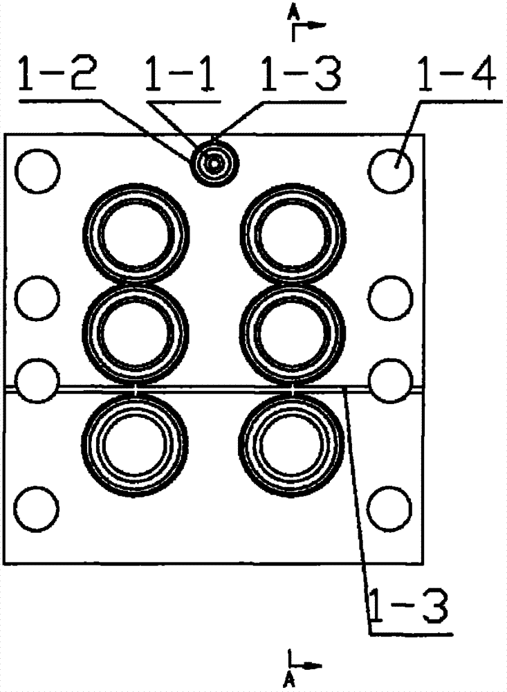
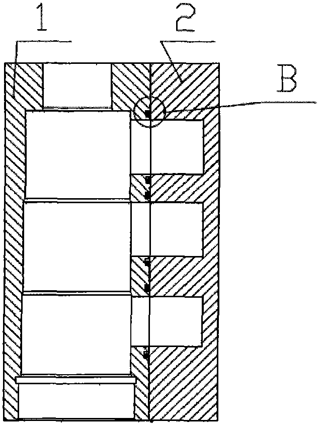
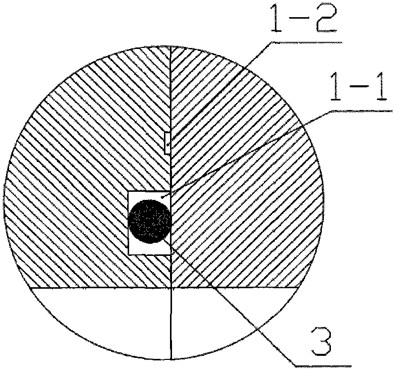
[0015] As shown in the drawings, the technical solution adopted by the present invention includes a valve body 1, a sealing groove 1-1 is processed on the contact surface of the valve body 1 in contact with the valve connecting plate 2, and an annular ring is processed outside the sealing groove 1-1. The unloading groove 1-2 is also processed with a linear unloading groove 1-3 communicating with the atmosphere on the contact surface of the valve body 1 in contact with the valve connecting plate 2, and the annular unloading groove 1-2 is connected with the linear unloading groove. Slots 1-3 are connected. exist figure 1 In the case shown, there are two annular unloading grooves 1-2 communicating with each other, and finally the linear unloading groove 1-3 communicating with the atmosphere is connected.

[0016] When in use, install the sealing ring 3 in the sealing groove 1-1, and connect the valve body 1 with the valve connecting plate 2 through the connecting screw installed...


PUM


Abstract

The invention discloses a sealed unloading groove between a valve body and a valve joint plate. The problems that high-pressure liquid is filled with the joint surface between the whole valve body and the valve joint plate once a rubber sealing ring between the conventional valve body and the valve joint plate is ineffective in sealing, so that high separation force is formed between the valve body and the valve joint plate, great tension failure is generated to a connecting screw between the valve body and the valve joint plate and lots of high-pressure liquid is injected outwards are solved. The sealed unloading groove is characterized in that an annular unloading groove and a linear unloading groove communicated with the atmosphere are formed on a contact surface of a valve body contacted with the valve joint plate. The sealed unloading groove between the valve body and the valve joint plate has the beneficial effects that the sealed unloading groove is simple in structure, safe and reliable, if ineffective seal is caused, the high-pressure liquid leaked at the ineffective seal can be discharged through the annular unloading groove and the linear unloading groove, namely the high-pressure liquid can be prevented from being filled with the joint surface between the whole valve body and the valve joint plate, and the phenomena that the sharply increased separation force between the valve body and the valve joint plate is caused and the tension failure is generated to the connecting screw between the valve body and the valve joint plate are avoided; and therefore, lots of high-pressure liquid is prevented from being injected outwards.

Description

technical field [0001] The invention belongs to the field of hydraulic technology, in particular to an unloading groove sealed between a valve body and a valve connecting plate. Background technique [0002] In coal mine hydraulic support valves, there is often a plate connection between the valve body and the valve connection plate. In the prior art, this type of plate connection is provided with a rubber sealing ring at the connection. If the seal fails, the high-pressure liquid will flow through the entire The joint surface between the valve body and the valve connection plate causes a large separation force between the valve body and the valve connection plate, which causes great tensile damage to the connecting screws between the valve body and the valve connection plate, and at the same time, causes a large amount of high-pressure liquid Spray outward. Contents of the invention [0003] The technical problem to be solved by the present invention is to overcome the d...

Claims


Application Information

Patent Timeline
Patent Type & Authority Applications(China)
IPC IPC(8): F16K27/00
Inventor 李继周
Owner BEIJING TIANMA INTELLIGENT CONTROL TECH CO LTD
Why Eureka
Try Eureka